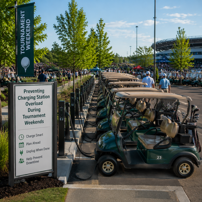

Do not plug every golf cart in at once. Before assigning charging bays, inventory every cart and charger, map each receptacle to its actual branch circuit, and build a circuit-by-circuit roster using each charger's AC input rating---not its battery-side output amps. If the planned simultaneous load exceeds verified site capacity or the charger manufacturer's requirements, add verified capacity or rotate carts through scheduled charging groups.
The goal is simple: keep carts ready for the next tee-time wave without tripped breakers, overheated connections, incompatible chargers, or rushed workarounds.
Build the Charging Inventory Before Assigning Carts

Treat tournament charging as a fleet operation, not a row of outlets. Guest carts, rentals, converted carts, spare chargers, and maintenance carts can change the electrical demand quickly.
Create one roster with a row for every cart that may need charging during the event.
| Roster Field | Record Before the Event |
|---|---|
| Cart ID | Fleet, rental, guest, reserve, or maintenance identifier |
| Battery System | Chemistry, pack voltage, and whether the cart has been converted |
| Charger | Model, connector, and approved battery application |
| AC Nameplate Data | Input voltage and input current shown on the charger label |
| Charging Bay | Physical parking and receptacle location |
| Circuit Assignment | Verified branch-circuit or panel identifier |
| Priority | Immediate turnaround, overnight, reserve, or hold |
| Status | Available, in use, charging, idle, or out of service |
Include cart age, battery type, maintenance history, and recurring operating problems in the pre-event review. This inventory exposes missing labels, unknown charger profiles, shared circuits, and carts that should not enter the common charging queue.
An inventory does not prove that a circuit can support the planned chargers. Site electrical personnel should verify branch circuits, receptacles, panels, and other building loads before tournament operations begin.
Plan From AC Input Current, Not Battery Output Amps

The charger's DC output or battery-side charging current describes what reaches the battery. It does not tell you the building-side load that must be supported by the receptacle, wiring, and branch circuit.
For infrastructure planning, use the charger's AC input voltage and AC input current from its nameplate or manufacturer documentation.
| Use for the Charging Roster | Do Not Use as a Substitute |
|---|---|
| Charger AC input-current rating | Battery amp-hour capacity |
| Verified circuit assignment | Cart range estimate |
| Other loads on the same circuit | Charger DC output current |
| Charger manufacturer requirements | A different charger model's rating |
This distinction matters because battery-side numbers can look familiar but answer a different question. In documented lead-acid charger versions, a 25 A charger can have an initial battery-side charge rate of 20--29 A, while a 10 A version can have an initial rate of 8--12 A. Neither figure is an AC input-current rating for circuit-capacity planning.
For each verified circuit:
- List every charger assigned to that circuit.
- Copy each charger's AC input-current value from its own label.
- Record other equipment that shares the circuit.
- Have qualified electrical personnel confirm the circuit's usable loading and whether the planned simultaneous charging is appropriate.
- Remove or rotate chargers when the circuit cannot support the roster.
Do not estimate a safe cart count from battery capacity, charger output amps, or the breaker label alone.
Map Circuits Before Choosing Bays or Rotations

A row of receptacles may look like several charging bays while actually being served by one branch circuit. Label each approved bay with its circuit ID and the charger or charger type permitted there.
One manufacturer's guidance for a 120 V, 60 Hz golf-cart charger application calls for each charger to have its own dedicated, separately protected 15 A or 20 A branch circuit and says not to place two chargers on one 15 A or 20 A circuit. That is manufacturer-specific guidance, not a universal rule for every charger or installation. Still, it illustrates why a physical bay map must be tied to the actual charger documentation and verified electrical layout.
Use this decision path:
- One charger, verified bay, approved circuit: Add it to the charging roster.
- Two planned bays on the same circuit: Do not assume both chargers may run together. Check the installed charger requirements and confirm site capacity.
- More carts than verified bays: Create charging groups rather than adding strips, splitters, or improvised adapters.
- Demand exceeds the recovery window: Arrange additional properly verified circuits, receptacles, or managed charging before the event.
- Circuit mapping is uncertain: Hold that bay out of service until qualified personnel verify it.
A pre-event test is essential. Run the planned charging groups under normal site conditions before tournament weekend, rather than discovering conflicts when carts return from the course.
Schedule Charging Around Real Recovery Windows
Not every cart needs the same charging time. For the documented lead-acid charger, charge duration varies with battery size and depth of discharge. Initial charge behavior can also vary with battery condition, depth of discharge, and available AC voltage.
That means a fixed promise such as "all carts will be ready in two hours" is not a reliable fleet plan.
Instead, divide the schedule into operational windows:
Post-Round Turnaround
Assign the first available charging bays to carts needed for the next tee-time wave. Mark carts that need immediate recovery and keep a separate status for those awaiting a later rotation.
Overnight Charging
Use verified overnight bays for carts expected to stage first the next morning. Confirm completion before staff leave the charging area and again before morning deployment.
Pre-Staging Checks
Before carts are released, update each cart's status as available, charging, idle, or out of service. A cart that has not completed charging should move to a backup decision---not quietly enter the day's assignments.
Keep reserve carts visible in the roster. A reserve is only useful if its battery system, charger compatibility, bay assignment, and readiness have been confirmed.
Make Lithium Conversion a Compatibility Gate
A lithium-converted cart should not be treated as a lead-acid cart with a different battery label. Verify the actual system before it enters the charging rotation.
A documented 24LC10-2ET charger is intended only for a 24 V, 12-cell series-connected lead-acid battery system. Its documentation does not establish compatibility with lithium, AGM, another lead-acid configuration, or a different pack voltage. Likewise, its maximum 20 A circuit-protection specification applies to that documented 115 V, 60 Hz charger---not to every charger in the fleet.
For every converted or mixed-chemistry cart, confirm:
- Pack voltage and battery chemistry
- Approved charger model and charging profile
- Charge-voltage and current limits from the battery manufacturer
- Connector compatibility
- Temperature restrictions and any battery-management-system behavior relevant to charging
- Charger settings that may be intended for lead-acid operation rather than lithium operation
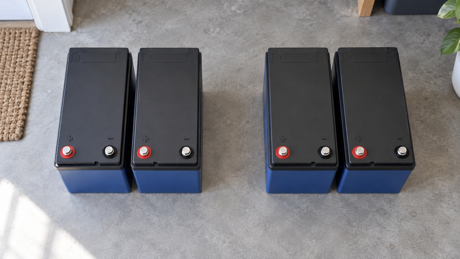
If any item is undocumented or unclear, mark the cart hold for review rather than assigning it to an available lead-acid bay. Where Vipboss LiFePO4 batteries are in the fleet, consult the applicable Vipboss battery charging documentation for charging limits, temperature conditions, BMS behavior, and approved charger configuration.
Keep Temporary Power From Becoming the Failure Point
A charging shortage is not a reason to create capacity with power strips, splitters, daisy-chained adapters, or unverified extension-cord arrangements. Overloading outlets or strips can overheat cords, strips, and building wiring.
Extension-cord guidance also warns that overloaded or improperly used cords can create fire hazards; connecting cords together increases resistance and heat generation. If temporary cords are unavoidable under site rules and qualified electrical direction, protect them from traffic and equipment damage and do not route them through doorways, windows, or walls. See this extension-cord and power-strip safety guidance.
The documented charger's instructions discourage extension-cord use and specify a grounded three-conductor No. 12 AWG electrical cord. Follow the instructions for the actual charger in service rather than treating one charger's documentation as a design rule for the entire fleet.
Define Stop Conditions Before the First Cart Returns
Give event staff authority to remove a bay from service and escalate rather than improvising a repair during a tee-time rush.
Stop charging and assess the bay when staff find:
- A tripped breaker or repeated loss of power
- A hot, discolored, damaged, or loose receptacle or plug
- A damaged charger cord or connector
- Abnormal charger behavior or repeated failure to complete charging
- A charger-to-battery pairing that is not documented as compatible
- A cart that cannot meet its assigned readiness window
Follow the installed charger's shutdown and disconnect procedure. For the documented charger, its DC connector should not be disconnected while the charger is on because of connector-arcing and battery-explosion risk.
For a breaker trip or suspected overload, do not move chargers to a power strip or another unknown outlet. Take the affected bay out of the roster, preserve the cart's status as unavailable or charging-delayed, and involve qualified electrical personnel for circuit, wiring, receptacle, panel, or temporary-power decisions.
Before tournament weekend, no cart should be assigned a bay until its battery chemistry, charger profile, connector, AC input demand, circuit assignment, and charging priority are verified in a documented site audit and charging roster.