
Lithium batteries can share a positive busbar and a negative busbar without sharing any information. That distinction is the reason communication matters.
When several battery modules operate together, each battery management system (BMS) is watching its own cells, temperature, current, and protection limits. Unless the batteries use a compatible communication architecture, the inverter or charger may see an incomplete or contradictory picture of the bank. A battery bank can be electrically connected yet poorly coordinated.
The practical idea is simple: power cables make the connection; communication lets the batteries and the rest of the system make coordinated decisions.
Parallel batteries share a load—not automatically a BMS
Connecting batteries in parallel increases available capacity and can increase the current the bank is designed to deliver. But each module still has its own BMS and its own local measurements.
Without an approved communication link, one battery may report a different state of charge—or no state of charge at all—than another. The inverter may then be unable to determine the bank’s usable limits. In addition, the modules may not know when another unit is warning, reducing output, or disconnecting.
Communication does not replace correct electrical design. Cable resistance, battery condition, fusing, busbars, and charge and discharge ratings still determine how current flows. Communication adds the coordination layer above that hardware.
What the batteries need to communicate

A multi-battery system may exchange some or all of the following information:
- State of charge (SOC): an estimate of how full each module is and, where supported, the combined bank.
- Voltage and current: measurements that help the system understand present operating conditions.
- Temperature: important when charging or discharging conditions must be reduced or stopped.
- Charge and discharge limits: the maximum voltage or current the BMS currently permits.
- Warnings and faults: such as overvoltage, undervoltage, overtemperature, or a protection event.
- Operating state and identity: whether a module is charging, discharging, idle, or in a fault state, plus information used to recognize the device on the network.
This information is useful because limits are not always fixed. A BMS may change what the charger or inverter should do when a cell reaches a voltage threshold or a temperature moves outside the permitted range. A communication guide from Avepower’s battery communication overview describes this exchange as control data—not merely information for a display.
Why one battery often acts as the system voice
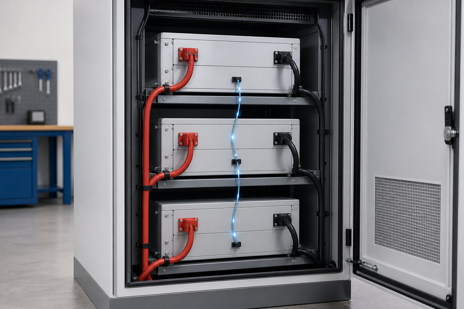
Many systems designate a master battery, gateway, or external battery controller. The individual modules send their data into that coordination layer, which presents a consolidated status and operating limits to the inverter, charger, or energy-management system.
That arrangement prevents the inverter from receiving several competing instructions. It also gives the system a defined path for responding to a fault. The exact architecture varies: some batteries communicate with one another and nominate a master; others use an external controller to monitor modules directly.
The important question is not whether a battery has a port labeled CAN or RS485. It is whether the battery, controller, inverter, firmware, addressing, cabling, and protocol settings are approved to work together. CAN and RS485 are communication methods, not guarantees of compatibility.
What can go wrong when communication is missing or incompatible?
The inverter may use the wrong limits
If the inverter cannot receive the bank’s current charge and discharge limits, it may rely on manual settings or a less complete control method. Those settings might not reflect the most constrained module at that moment. Follow the battery and inverter manufacturers’ instructions rather than assuming a generic voltage or current value is suitable.
State-of-charge readings can become confusing
SOC is an estimate produced from measurements and BMS logic. Different modules can show different values, especially if they have not been commissioned together or have different histories. If the system has no supported method of combining those readings, the number shown by the inverter may not represent the whole bank reliably.
One module can disconnect before the others
A local protection event can cause one BMS to open its charge or discharge path. The remaining batteries then see a changed load, and the inverter may not know why the bank’s available capacity suddenly changed. Communication can help the system respond deliberately, but it cannot make an unsuitable or unhealthy module safe to parallel.
Troubleshooting becomes guesswork
A communicating system can expose alarms, temperatures, limits, and module identity to compatible monitoring equipment. A system without that path may still run, but a fault can look like a mysterious inverter shutdown, a missing battery, or an unexplained imbalance.
Communication is only one part of a reliable bank

Treat communication as a compatibility requirement, not a cure-all. Before connecting modules, verify all of these items in the current manuals:
- Battery compatibility: Confirm that the manufacturer permits the batteries to operate in the proposed parallel or series arrangement. Do not assume that two batteries with the same nominal voltage are compatible.
- BMS architecture: Determine whether the modules communicate directly, through a master, or through an external controller.
- Protocol and firmware: Check the required protocol, device addresses, firmware versions, and inverter or charger compatibility.
- Communication topology: Follow the specified cable order, ports, daisy-chain or hub arrangement, termination, and maximum node count. These details are model-specific.
- Power-path design: Use the prescribed busbars, cable sizes, protection, and connection arrangement. Communication wiring does not correct unequal resistance or missing fuses.
- Commissioning state: Follow the required startup sequence and confirm that every module is recognized before placing a substantial load on the bank.
For example, one manufacturer’s VE.Bus BMS documentation specifies daisy-chaining BMS cables for several batteries and connecting the first and last cable to the BMS. That is useful evidence that communication topology matters—but it is not a universal wiring rule. The instruction for your battery system takes priority.
A safe way to think through a planned installation
Ask four questions before energizing the complete system:
Can the batteries communicate with each other? Look for a documented multi-battery mode, not just a communication socket.
Can the combined system communicate with the inverter or charger? The external device must understand the battery’s protocol and the limits it reports.
What happens if one module drops out? The documentation should explain alarms, isolation, and the expected system response.
How will you confirm the result? A proper commissioning check should show all modules, plausible voltages and temperatures, a consistent bank status, and no active communication or protection alarms.
If any answer is unclear, pause at the documentation stage. Do not experiment with random cables, unsupported protocol converters, or mixed batteries to see whether the system starts.
The bottom line
Multiple lithium batteries need to talk because a battery bank is a coordinated electrical system, not merely a pile of voltage sources. Each BMS knows important facts about its own module; communication allows those facts and changing operating limits to reach the other batteries and the equipment controlling them.
The correct setup is therefore not simply “connect the positives and negatives.” It is: choose a supported battery arrangement, build the power path correctly, connect the approved communication network, and verify that the inverter or charger recognizes the bank. When the manuals do not explicitly support the combination, treat that uncertainty as a stop sign—not as an invitation to guess.