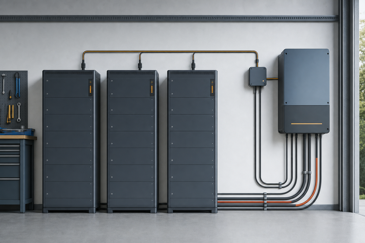

Communication errors between paralleled battery banks are rarely solved by swapping cables at random. The useful question is where the data path fails: at the bank’s power supply, physical wiring, bus topology, node identity, protocol settings, or the battery-management system itself. Work from those layers in order, and separate a communication fault from a battery protection event that merely looks like one.
First, identify what has actually failed
Record the symptom before changing anything:
- One bank disappears: suspect that bank’s power, cable, connector, address, or communication port.
- All banks disappear: suspect the gateway, inverter connection, shared bus, termination, protocol selection, or a common power source.
- The system connects, then drops out: inspect loose contacts, electromagnetic interference, marginal power, incorrect termination, and excessive cable length or branching.
- The banks are visible but data conflicts: look for duplicate addresses, mixed firmware or battery models, incompatible protocols, or a bank configured as the system’s primary or leader incorrectly.
- Charging or discharging stops at the same time: check for a BMS protection event or loss of the enable/limit data path, not just a data cable fault.
Save screenshots or error codes and note whether the failure occurs at startup, under charge, under load, or after the system has been running. That timing is valuable evidence.
Safety and compatibility come before testing
Battery terminals can remain energized even when an inverter or display is off. Follow the battery, inverter, and gateway manuals; use insulated tools and appropriate protective equipment; and have qualified personnel perform work inside energized equipment. Do not unplug, repin, or rearrange communication connectors while equipment is powered unless the manufacturer explicitly permits it.
Confirm that the battery models, firmware families, inverter or charger, and communication gateway are approved to work together. “Parallel” on the power side does not automatically mean that the banks can share a BMS network. Some systems require a particular master/leader arrangement, gateway, cable, or protocol, while others cannot be mixed at all.
Model-specific details matter: RJ45-shaped connectors do not guarantee identical pinouts, and CAN, RS-485, proprietary battery buses, and Ethernet are not interchangeable simply because they use similar plugs. Use the exact cable and pin assignment specified by the manufacturer.
Use isolation to find the failing node

A repeatable isolation test is more informative than repeated resets. With the system made safe according to its manuals:
- Photograph and label every cable, terminator, switch, and address setting.
- Disconnect the parallel communication network from the inverter, gateway, or monitor and reconnect it exactly as specified. If the fault affects every bank, this separates a battery-side network problem from the external device or its cable.
- Test with one known-compatible bank connected. If it works alone, add the other banks one at a time.
- When the fault returns, swap only one variable—such as the network lead or port—with a known-good equivalent. Do not change the address and cable simultaneously.
- If one bank fails when connected but the others work, remove it from the network and inspect that bank’s power state, connector, address, and firmware against its manual.
A bank that is electrically connected but powered down may still interrupt some network designs. Conversely, disconnecting a bank may create an open circuit or remove a required terminator. Follow the manufacturer’s permitted isolation procedure rather than improvising a topology.
Check the physical network layer

Start with a visual inspection under power-off conditions where the manual requires it. Look for a cable in the wrong port, reversed conductors, bent contacts, damaged latch tabs, corrosion, tight bends, and connectors that are not fully seated. Route communication cables away from high-current battery and inverter conductors where practical, and restore any specified shield or reference connection.
Then verify the network shape. CAN and many RS-485 systems are line networks: devices connect along a main run, not through unlimited star branches. Keep stubs short if the manufacturer specifies that requirement. Check that the two ends of the actual bus—not simply the first and last batteries in a cabinet—are terminated as the manual shows.
For a conventional CAN network, a power-off resistance test between CAN-H and CAN-L can be useful. Two 120-ohm end terminators appear as approximately 60 ohms in parallel; approximately 120 ohms suggests one terminator, and a substantially lower reading can indicate an extra terminator or a wiring fault. This test is not universal: internal, switched, or intelligent termination changes what a meter should show. Use the device manual before interpreting the number; a CAN troubleshooting guide describes the test and its limitations in detail.
RS-485 networks also depend on correct polarity, topology, termination, and—depending on the protocol—biasing. Do not add resistors because a generic guide recommends them. Confirm whether termination or bias is built into the battery, gateway, or inverter and whether the manufacturer specifies where it belongs.
Confirm power, identity, and configuration
Communication hardware needs a valid supply. Check the bank’s status indicators and the gateway’s supply according to their documentation. A battery in sleep, standby, low-voltage protection, or a latched fault state may not present its communication interface normally. Resolve the underlying battery state first; do not repeatedly power-cycle a bank that is reporting an unresolved protection condition.
Next compare configuration records:
- Every node that requires an address has a unique address.
- The designated leader, master, or terminator settings match the wiring diagram.
- All banks use the same required nominal voltage, battery family, and supported communication protocol.
- The inverter or gateway is set to the protocol expected by the battery network.
- CAN bitrate, RS-485 mode, baud rate, parity, and device role match where those settings are user-configurable.
- The monitoring device is connected to the correct bus or gateway port, not a service, programming, or unrelated network port.
A duplicate address can produce an intermittent or misleading result because both devices may answer as if they were the same node. Change only one address at a time and record the original values so the installation can be restored.
Distinguish communication errors from power faults
Compare the communication alarm with electrical measurements and BMS events. A bank can stop accepting charge because of overvoltage, low temperature, overcurrent, cell imbalance, or another protection limit while the communication link remains healthy. A display that shows stale state of charge may indicate lost data, but it does not by itself prove that the battery has stopped delivering power.
Look for these patterns:
- Live voltage and current data, but no state-of-charge or limits: the physical link may work while protocol mapping, firmware compatibility, or gateway configuration is wrong.
- No data and no status light: check bank power, wake-up conditions, fuse or breaker state, and the communication cable.
- Data disappears only under high load: inspect voltage drop, grounding/reference issues, electromagnetic interference, and a marginal power supply to the gateway.
- One bank reports a protection event while others communicate: treat that bank’s BMS condition first; do not replace the shared bus automatically.
Never bypass a BMS, protection device, or charge limit to “prove” that communication is the problem.
When firmware or replacement is justified
Firmware can matter when the manufacturer documents a compatibility requirement or a known communication fix, but update only after recording the current versions and confirming the exact battery and gateway procedure. Keep power stable during an update, and do not interrupt it. A firmware update is not a substitute for correcting an incorrect pinout, address, terminator, or protocol.
Escalate to the manufacturer or a qualified service technician when the fault persists with a verified cable, correct topology, valid power, unique addresses, and a known-compatible single-bank test. Provide the model and serial information, firmware versions, wiring diagram, error logs, photos of the network layout, and the exact step at which the fault returns. If one bank consistently brings down a correctly configured network, the evidence points toward its connector, transceiver, internal termination, or BMS communication interface—but that conclusion should be confirmed through the manufacturer’s diagnostic process.
The fastest reliable sequence is therefore: prove compatibility, document the symptom, make the installation safe, test one bank, inspect the cable and topology, verify termination, check power and addresses, confirm protocol settings, and only then investigate firmware or hardware failure. That order prevents a communication alarm from turning into unnecessary rewiring—or an unsafe attempt to override a battery protection system.
For a conventional CAN termination reference, see this power-off CAN bus resistance procedure. For model-specific battery networking, use the manufacturer’s installation and communication manual, not a generic cable diagram.