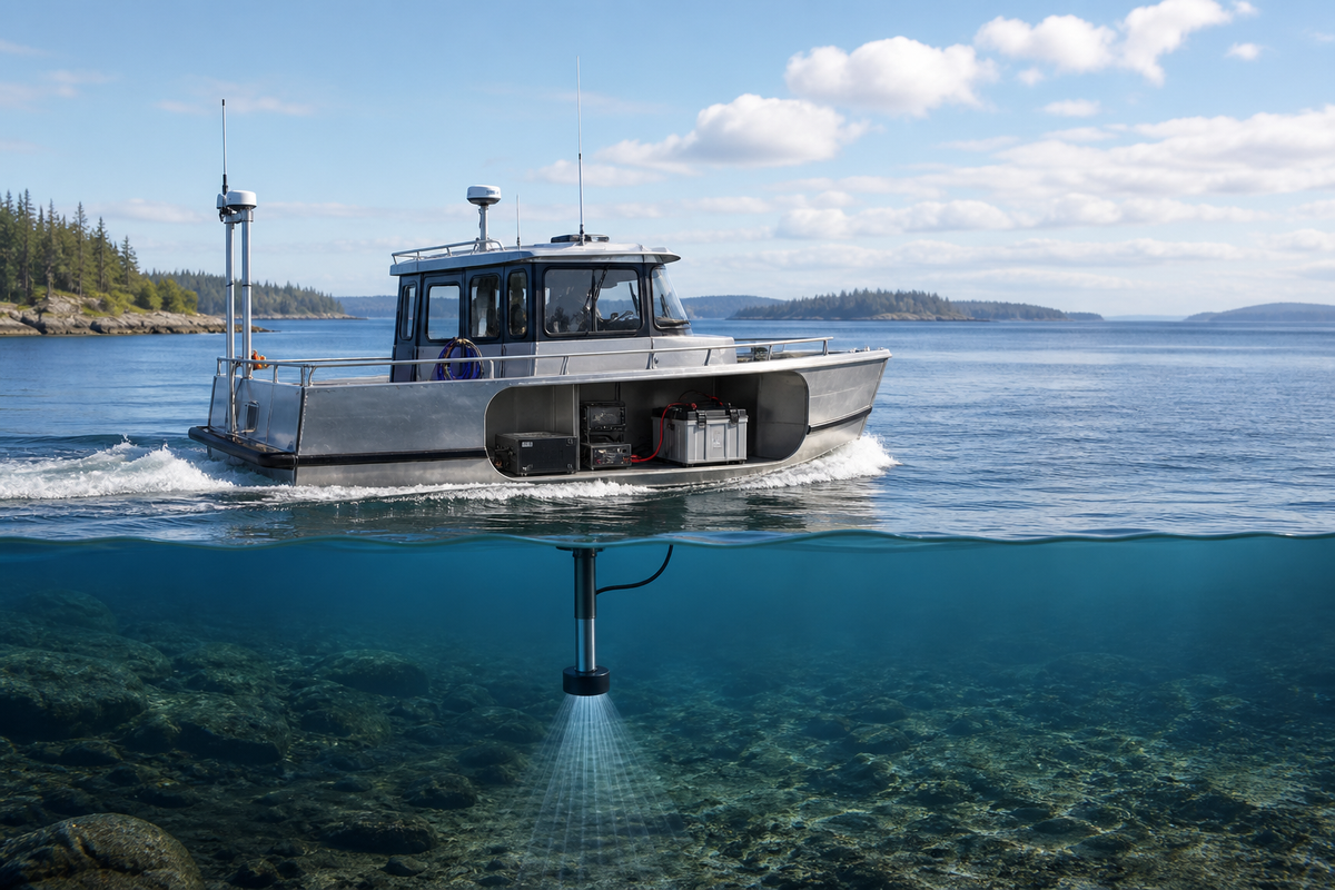

Small research vessels rarely fail a survey because the battery label was too small. More often, the payload shares a poorly planned circuit with a thruster, alternator, winch, or inverter—and the result is voltage sag, electrical interference, unexpected shutdowns, or lost data.
The reliable approach is to design power as part of the survey system. Start with the actual equipment manuals, separate the sensitive payload from noisy loads, protect and size every conductor correctly, and prove the installation at the dock and underway.
Start with the survey payload, not the battery

Make a load table before choosing batteries or converters. List each item, its specified input voltage, typical power or current, startup surge, duty cycle, and whether it must remain online:
- sonar head, sounder, or transceiver;
- processing computer and display;
- GNSS, motion reference, sound-velocity, and heading sensors;
- network switches, serial or USB interfaces, and data storage;
- transducer pole, winch, lights, and communications equipment used during acquisition; and
- chargers, DC-DC converters, inverter loads, and any cooling fans.
Use the highest credible operating case, not the average from a calm day. A computer may draw more while processing than while displaying; a sensor may have a brief startup demand; and a towfish or winch can create a large transient. The equipment manual is the authority for those values.
NOAA’s equipment descriptions illustrate why “sonar” is not one electrical load: survey platforms may combine multibeam, single- or vertical-beam, and side-scan systems, in hull-mounted or towed configurations. NOAA’s overview of hydrographic survey equipment is a useful reminder to inventory the complete acquisition chain rather than size power for the transducer alone.
Convert the load table into an energy budget
For each load, calculate energy over the planned survey window:
watt-hours = watts × hours of operation
If a device is specified in amps, calculate approximately:
watts = volts × amps
Then account for conversion losses. An inverter or DC-DC converter cannot deliver its output rating from the battery without drawing additional input power. Use the converter manufacturer’s efficiency and idle-consumption figures where available; otherwise, label the estimate as provisional rather than promising a runtime.
Add a reserve for weather, delays, battery temperature, aging, and the portion of the battery that the manufacturer permits you to use. Do not treat nominal battery capacity as guaranteed usable energy. The battery-management system, low-voltage cutoff, discharge rate, temperature, and charging limits can all change the result.
Keep two numbers separate:
- Continuous demand: what the system draws while the survey is running.
- Peak demand: what must be supplied when equipment starts, motors move, or loads change suddenly.
A bank can have enough watt-hours for a day and still trip a protection device if it cannot supply a peak current. Conversely, a high-current bank does not solve an energy shortfall.
Choose an architecture that fails gracefully
For many small vessels, the cleanest arrangement is a dedicated survey-power branch from the vessel’s DC system, with its own main disconnect, overcurrent protection, distribution, monitoring, and appropriately rated converters. The propulsion and hotel loads remain on their normal circuits.
A separate survey battery bank can improve isolation when the vessel has frequent engine starts, electric propulsion, thrusters, high-current winches, or an alternator known to produce interference. It also gives the operator a clearer answer to “how much survey time remains?” But separation adds weight, charging hardware, space, and another system to maintain. Decide from measured interference and operational consequences—not from the battery chemistry alone.
Use the equipment’s specified voltage whenever practical. Converting a vessel’s 12- or 24-volt supply to AC and back to DC adds loss, heat, another failure point, and possible waveform or grounding complications. If an AC-only instrument requires an inverter, select a marine-suitable unit whose output, surge capability, grounding arrangement, and installation environment match the instrument and vessel. Confirm the complete chain with the equipment manufacturer.
Design for a controlled shutdown. Critical data should be saved before a low-voltage disconnect acts, and the operator should see an alarm early enough to end a line safely. A backup supply may be worthwhile for the computer, navigation reference, or network equipment, but it should not be assumed to support the sonar unless its capacity and transfer behavior have been tested.
Treat wiring and protection as part of the instrument
Marine wiring faces vibration, moisture, salt, heat, and corrosion. Use marine-rated stranded conductors, terminals, connectors, supports, and enclosures appropriate to the location. Keep connections dry and inspectable; protect cables from chafe and avoid routing signal cables alongside high-current motor or alternator conductors for long runs.
Size each conductor by both ampacity and allowable voltage drop. The larger size required by those two checks governs. For a critical electronic load, even a small drop can matter if the equipment is near its low-voltage limit. Account for the complete round-trip cable length, connector losses, temperature, bundling, and the converter’s input current—not just the distance from the panel to the instrument. A concise marine DC wiring reference covering voltage drop and overcurrent principles can help frame the calculation, but the vessel’s applicable rules and a qualified marine electrician control the installation.
Protect every branch with an appropriately rated fuse or breaker. Place the main battery-side protection as close to the source as the applicable standard and installation instructions require, then protect downstream conductors and equipment according to their ratings. A fuse is not a substitute for correct wire sizing, and a larger fuse is not a cure for nuisance trips. Never choose a fuse solely from the instrument’s normal current: check startup behavior, conductor ampacity, interrupt rating, and the equipment manual.
Provide a clearly labeled disconnect for the survey bank or distribution panel. Use a shunt or other suitable monitor if you need trustworthy current and state-of-charge information, and ensure its installation does not bypass required protection.
Keep propulsion noise out of the data

Sonar quality depends on more than available energy. Alternators, engine ignition systems, motor controllers, thrusters, pumps, inverters, poorly bonded shields, and long return paths can inject conducted or radiated noise. Symptoms include bands, spikes, dropouts, unstable sensor links, or interference that changes with engine speed.
Use a single, intentional power-return and grounding strategy consistent with the equipment manuals. Avoid improvised negative connections between distant panels. Separate high-current switching paths from transducer, Ethernet, serial, GNSS, and motion-sensor cables. Cross unlike cable types at right angles where they must intersect, and keep cable shields and bonding arrangements exactly as specified by the manufacturer; indiscriminate grounding can create loops.
Add filtering, ferrites, isolation, or a DC-DC converter only when the problem and its electrical location are understood. A filter that helps one frequency may not address a motor transient. Test first with the engine and suspect loads in the combinations used during a survey, then change one thing at a time and document the result.
Battery selection is a system decision
Compare batteries on usable energy, continuous and peak current, temperature limits, charge profile, protection behavior, physical mounting, serviceability, and the vessel’s charging sources. The charger, alternator interface, solar controller, DC-DC charger, and battery-management system must be compatible as a system.
Install any battery according to its manual and applicable marine requirements. Secure it against movement, protect terminals from accidental shorting, keep it away from heat and water ingress, and provide the ventilation or enclosure arrangement required for that battery and its charging equipment. Lithium systems may have different ventilation and charging requirements from lead-acid systems, but “sealed” does not mean “safe anywhere.” Chargers and inverters still produce heat, and every battery system needs suitable fault protection.
Do not place a battery-bank promise ahead of mass and trim limits. On a small vessel, the bank, enclosure, cabling, and protection hardware can affect stability and deck loading. Have the complete arrangement reviewed when the installation is beyond a straightforward service replacement.
Verify it before collecting valuable lines
Run an acceptance test with the final cable lengths, connectors, software, and sensors installed:
- Record battery voltage at rest and at the distribution point.
- Measure voltage at the equipment input during normal operation and the highest expected load.
- Start and stop the engine; operate alternators, pumps, thrusters, winches, radios, and inverters in realistic combinations.
- Watch for sonar dropouts, data corruption, network resets, sensor alarms, and visible noise in the acoustic record.
- Confirm that each protective device, disconnect, converter, and charger behaves as intended without overheating.
- Check cable supports, terminal temperature, enclosure ventilation, and battery restraint after a loaded run.
- Test the low-voltage alarm and planned shutdown while recording what data remains recoverable.
Repeat the check at the actual survey speed and with the payload deployed. A system that is quiet at the dock may change when the transducer, tow cable, or engine operating point changes. Keep a simple commissioning record: load readings, battery state, engine condition, interference observations, and corrective changes.
A practical design rule
The best small-vessel survey power system is not necessarily the largest battery. It is the one whose loads are known, peaks are accommodated, sensitive equipment is electrically separated from noisy machinery, conductors are protected and sized for the real route, and remaining runtime is visible to the operator.
If the design involves a new high-current bank, an inverter, lithium charging integration, an altered engine-start system, or uncertain grounding, stop at the calculation stage and involve a qualified marine electrician and the equipment manufacturers. Reliable survey data—and safe operation—are worth more than a speculative capacity figure.