
Check an RV SAE solar port by measuring polarity at an accessible energized source, then mapping each suitable, isolated passive wire path with a de-energized continuity test. Mark the source contacts positive and negative from the voltage reading, follow each identity through the recorded input-to-output pairs, and compare the resulting equipment-end polarity with the mating equipment's documented requirement. A reversal adapter is appropriate only if its documented mapping corrects the measured mismatch; the SAE shape alone does not establish polarity.
Identify what the port connects to
An RV solar-prep port may run directly to the battery or connect through a controller or other components. The label and appearance do not identify your RV's route. Check the RV documentation or follow wiring only where it is accessible; do not open or probe unidentified circuitry to find the route. Common solar-ready arrangements provide context, but cannot identify your RV's wiring.
A voltage reading describes the point tested, not the entire circuit. A reading at the exterior port tells you the polarity there under the test conditions; it does not show whether the port goes directly to the battery or through a controller. Record the downstream route as unknown if documentation or accessible wiring does not resolve it.
Measure polarity at the energized source
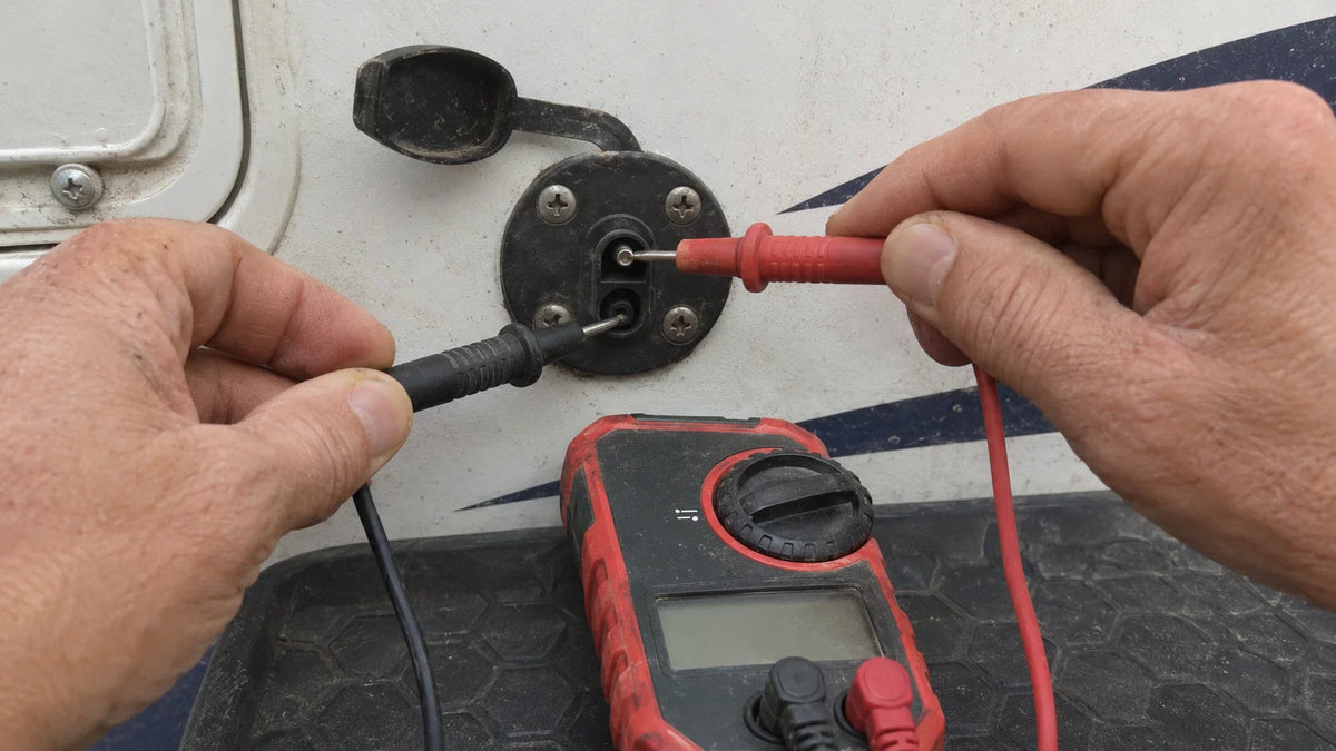
Set up the meter. Use a digital multimeter set to DC volts. Put the black lead in COM and the red lead in the voltage input, not an amperage input. At an accessible test point with identifiable positive and negative contacts, place the black probe on negative and the red probe on positive. This is the standard DC-voltage measurement method.

Read the sign. A positive reading means the red probe is on the positive point relative to the black probe. A negative sign means the red probe is on the negative point relative to the black probe. The sign describes those test points, not the wiring route beyond them.
Only measure points you can identify and reach safely. If the port is inaccessible, damaged, or part of unidentified circuitry, do not probe it; mark its polarity undetermined. A port-only reading does not identify the polarity mapping of a separate lead or adapter.
Map a suitable isolated wire path
Use continuity mode only on a passive individual wire path that is electrically isolated from circuitry, with power off and capacitors discharged. The path's contacts must be accessible and identifiable. If you cannot establish those conditions, do not test it; mark its mapping unresolved. A continuity test on an individual wire path shows which contacts connect end to end, but continuity does not label either contact positive or negative.

Record the contact pairs. Put the black lead in COM and the red lead in the meter's voltage/ohms input, then select continuity mode. Test each input contact against the output contacts and record which pair indicates continuity. Repeat for the other input contact. For example, record “input A to output B” and “input B to output A” if those are the pairs that connect. Do not assume a contact's polarity from its SAE shape.
Carry the source identities through the pairs. Use the DC-voltage result to label the source contacts positive and negative. Then follow each label through the recorded continuity pairs: if source positive enters input A and A connects to output B, output B carries that positive identity; follow source negative the same way. Compare the resulting output positive and negative contacts with the mating equipment's documented requirement. The path preserves polarity if the required identities arrive at the corresponding contacts; it reverses polarity if they arrive at the opposite contacts. Continuity supplies the contact mapping; the voltage test supplies the source identities.
Apply this method to a lead or adapter only when it is a suitable passive, isolated wire path and its contacts can be mapped under those conditions. If circuitry remains connected, capacitors may not be discharged, or contacts cannot be identified, continuity cannot establish its mapping or resulting polarity.
Decide whether a reversal adapter fits
First compare the measured source polarity, carried through each known lead mapping, with the mating equipment's documented requirement. If they match, a reversal adapter is not needed to correct polarity. If they do not match, use an adapter only when its documented input-to-output mapping swaps the relevant positive and negative identities to meet that requirement. Where the adapter is a suitable isolated passive path, map it with the same continuity method and follow the identities through its recorded pairs before connecting equipment. Otherwise, its mapping remains unresolved.
One solar-kit manual specifies contact polarity for that kit's SAE adapter and recommends a polarity adapter when needed to match its battery-side connection. That documented orientation applies to the kit described in the manual, not to every SAE port or adapter.
The result should be a documented polarity match, a documented adapter correction supported by the measured source and contact mapping, or an unresolved polarity or route. Do not connect solar equipment based only on connector shape or an incomplete measurement.
FAQs
Does an RV SAE port's voltage reading show where the port is wired?
No. It establishes polarity at the tested points under those test conditions, but the route to the battery, controller, or other components must be identified from RV documentation or accessible wiring.
How do you tell whether a lead or adapter preserves or reverses polarity?
When it is a suitable passive wire path isolated from circuitry, with power off, capacitors discharged, and contacts accessible, use continuity mode to record which input contacts connect to which output contacts. Follow the source's positive and negative identities through those pairs and compare the output with the mating equipment's documented polarity requirement.
When should you use a polarity-reversing adapter with an RV SAE solar port?
Use one only when the measured connection-chain polarity mismatches the mating equipment's documented requirement and the adapter's documented mapping corrects that mismatch. If the route, mapping, or required polarity is unresolved, do not connect based on the SAE shape alone.