
Read 12V LiFePO4 BMS current rating together with its direction and duration. Continuous discharge current limits loads that keep running. Peak discharge current applies only for the stated seconds. Maximum charge current limits current flowing into the battery. An overcurrent or short-circuit threshold tells you when protection may disconnect the battery; it is not a normal operating target. Start by comparing your highest simultaneous battery-side current with the continuous rating, then compare startup surge with both the peak current and its time limit.
Continuous, peak, charge, and trip ratings do different jobs
Battery listings do not always use identical labels, but these four meanings should stay separate.
| Rating | What it means | What to compare with it |
|---|---|---|
| Maximum continuous discharge current | The highest current the battery and BMS are rated to supply continuously under their specified conditions | All loads that can run at the same time |
| Peak discharge current | A short burst allowed for a stated duration | Motor, compressor, pump, or inverter startup surge |
| Maximum charge current | The highest permitted current entering the battery | The combined output of active chargers |
| Overcurrent or short-circuit trip | A protection threshold, usually combined with a detection delay | Fault behavior, not planned operating current |
A BMS measures pack conditions and can open its charge or discharge switches when a protection limit is reached. Current-protection designs distinguish charging overcurrent, discharging overcurrent, and short circuits; some also apply different thresholds and delays before disconnection. That is why a trip value cannot replace a continuous rating or a time-limited peak value. The distinction is visible in BMS protection functions for LiFePO4 packs and in configurable overcurrent thresholds and delays.
Convert the load into battery-side current

For a direct 12V load, use its maximum current rating or measured worst-case current. For an inverter load, estimate battery current with:
Battery current = AC output power ÷ (loaded battery voltage × inverter efficiency)
Use the inverter’s specified efficiency and a realistic low loaded voltage, not only the battery’s 12.8V nominal value. Conversion losses make input current higher than watts ÷ volts; the same power relationship is expressed in converter input-current guidance.
Consider an illustrative 1,000W inverter operating at 90% efficiency with 12.0V at its DC input:
1,000W ÷ (12.0V × 0.90) = 92.6A
That leaves only 7.4A below a 100A continuous BMS limit. If lights, a refrigerator, or another DC load adds 8A at the same time, the combined current becomes about 100.6A. Reduce the simultaneous load or use a system with a higher verified continuous-current limit.
A 1,200W load under the same assumptions would require about 111A. A brief 111A startup event might fit a separately stated peak rating, but a continuous 1,200W load does not fit a 100A continuous limit.
A peak rating works only for its stated time
Suppose a motor draws 180A for one second and then settles to 45A. It fits a battery rated for 100A continuous and 200A for five seconds only if the equipment data supports those numbers under the installation conditions. The same 180A surge would not fit a 150A peak rating, and a 180A load lasting ten seconds would not fit a five-second allowance.
Do not assume that a peak number means the BMS will deliver exactly that current before it disconnects. Cell voltage, state of charge, temperature, wiring resistance, and the BMS protection settings can cause a low-voltage, temperature, or overcurrent shutdown first. If the listing gives a peak current without a duration, treat it as incomplete information.
Charge current is a separate limit
Add the output of charging sources that may operate together. A 40A shore charger and a 30A solar controller could send up to 70A toward the battery when both are active. Compare that total with the battery’s maximum charge current and with any lower recommended charge rate.
Do not use the discharge rating as the charge limit. A BMS may use separate sensing and protection for current flowing into and out of the pack, so the two ratings can differ.
Read the ratings as one set

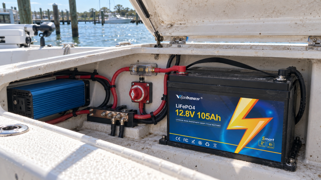
The Vipboss 12V 105Ah LiFePO4 battery is a useful example because its published current limits separate 100A continuous discharge, a 350A peak lasting 3–5 seconds, 100A maximum charging, and a 21A recommended charging current.
For any battery, make the same four checks: total the continuous loads, identify surge current and duration, total simultaneous charging current, and keep protective trip thresholds out of the operating plan. If a required value or duration is missing, ask the battery or equipment manufacturer before choosing the system.