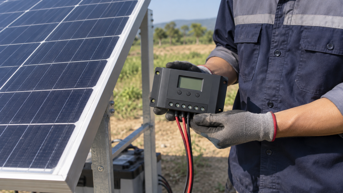

Choose the controller by matching the battery-bank voltage, the solar array specifications, the controller’s charging-current rating, the controller’s LiFePO4 support, and the battery’s maximum charge current. Start by recording the battery and panel specifications, then calculate the expected charging current and compare the array voltage with the controller’s input limits. Keep the selection only when every listed limit and the required charging profile are compatible.
Confirm the battery-bank voltage and charge limits
A controller must support the battery bank’s actual configuration. A single 12V-class LiFePO4 battery is usually used in a 12V system; batteries wired in series create a higher-voltage bank, while parallel wiring increases capacity without changing nominal voltage. Do not choose from the battery’s amp-hour label alone.
Check the battery documentation for the recommended charging voltage and maximum charging current. The controller must stay within both limits. A battery’s built-in BMS can protect against some unsafe conditions, but it is not a substitute for configuring the controller correctly.
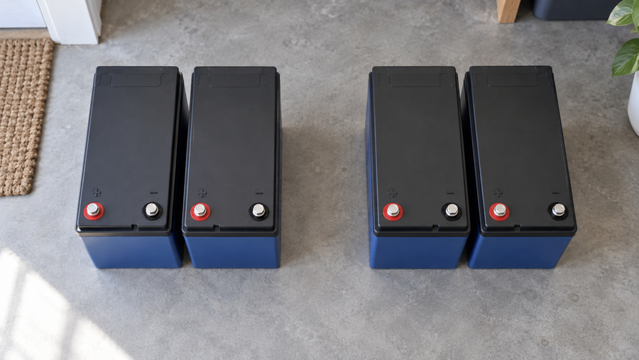
The Vipboss 12V 105Ah Bluetooth LiFePO4 battery may be relevant to a 12V solar design. Before selecting the controller, use the battery documentation to confirm its maximum charging current, final charging-voltage limits, and any low-temperature charging restrictions. Its Bluetooth monitoring can help you observe battery status, but it does not replace correct controller configuration.
Calculate the controller’s charging current
For an MPPT controller, estimate the maximum battery-side charging current by dividing the array’s rated power in watts by the battery charging voltage in volts:
estimated charging current (A) = array power (W) / battery charging voltage (V)
Use the watts-equals-volts-times-amps relationship, as demonstrated in this battery-charging calculation. Use charging voltage from the battery documentation, not the battery’s nominal-voltage label.
For example, a 400W array and a 14.4V charging voltage give an ideal estimate of 400W / 14.4V = 27.8A. The controller’s continuous charging-current rating must be at least the calculated requirement, including any sizing margin required by its manufacturer. Its maximum PV input power must also accept the array, and the configured charge-current limit must not exceed the battery’s maximum permitted charging current. The estimate is a sizing check, not a promise of actual output; available solar power and conversion losses can reduce real charging current.
Choose MPPT or PWM for the array

Base this choice on the array’s operating voltage, not on the type name alone. A PWM controller requires a voltage-matched array whose documented operating range is suitable for the battery bank. Choose MPPT when the planned array operates at a higher voltage than the battery bank, such as panels wired in series, because an MPPT controller can convert the higher PV input voltage to the battery’s charging voltage. This higher-voltage condition requires MPPT and is also documented in this comparison of PWM and MPPT regulators.
Before choosing PWM, verify in that controller’s documentation that the panel Vmp is suitable across the battery’s charging-voltage range and that array short-circuit current stays within the controller rating. Before choosing MPPT, verify that the array Vmp falls inside its MPPT operating window and that the worst-case array Voc stays below its maximum PV input voltage. For either type, reject the controller if it lacks the required LiFePO4 profile or configurable charging values.
Check panel voltage before current rating
Build the planned array on paper before approving a controller. Add panel Voc values for modules in each series string and compare the temperature-corrected string Voc with the controller’s maximum PV input voltage. For parallel strings, total the input current as directed by the controller manufacturer. Also confirm that total array wattage does not exceed the controller’s permitted PV input power for the selected battery-bank voltage.
These are PV-input checks, separate from the battery-side charging-current calculation. A controller fails the match if any planned string falls outside its documented MPPT operating window or PV voltage, current, or power limit.
Match the settings to LiFePO4 chemistry
Select the controller’s LiFePO4 profile when one is available. If the controller is configurable, use the charging values supplied for the specific battery rather than selecting settings without checking the battery documentation.
Verify that the controller documentation covers the charging settings required by the battery, including any applicable absorption, float, low-temperature charging, and temperature-compensation controls. If the controller cannot be configured for the battery’s required profile, choose another controller.
Do not assume that a BMS makes every controller setting acceptable. The BMS is a protection layer; the controller still needs to be configured for the battery’s required charging voltage and current.