
A 12V LiFePO4 system handles high loads reliably only when the battery, BMS, cables, fuse, connections, and inverter can support the same demand. Start by converting the load into DC current, then measure voltage at both the battery terminals and the load while it is running: if the battery stays healthy but the load-side voltage falls much farther, the wiring path is the problem; if both readings fall sharply or the BMS disconnects, the battery bank or operating condition is limiting output.
Convert the load into battery current

For a direct 12V load, use:
Current (A) = Power (W) / Voltage (V)
For an inverter load, include inverter losses:
Battery current (A) = AC load power (W) / (battery voltage (V) x inverter efficiency)
These are planning estimates. Use the equipment’s running-current and startup-current specifications when they are available.
For an illustrative 600W AC load through an inverter operating at an assumed 90% efficiency and 12.8V battery voltage:
600 / (12.8 x 0.90) = about 52A
That is a substantial continuous load for a 12V system. A motor, compressor, pump, or other inductive appliance may briefly demand more during startup. A battery can have enough stored energy for the runtime and still fail to start the load because its BMS, terminals, cables, fuse, or inverter cannot support the short surge.
Treat amp-hours as an energy and runtime figure, not as an output-current rating. Before approving a load, find the battery’s continuous discharge limit, surge limit, BMS behavior, and the limits of every current-carrying component.
Check voltage at the battery and the load

Voltage drop is the difference between the source voltage and the voltage delivered to the equipment while current is flowing. Resistance in cables, lugs, fuses, disconnects, busbars, and switches turns part of the battery voltage into heat and reduces the voltage available to the load.
Use a multimeter or suitable monitoring equipment to take two readings during the same load event:
Measure directly across the battery terminals.
Measure at the inverter or DC load input terminals.
Subtract the load-side reading from the battery-side reading.
Repeat during startup if the equipment has a surge.
Check whether cables, terminals, fuse holders, or disconnects become unusually warm.
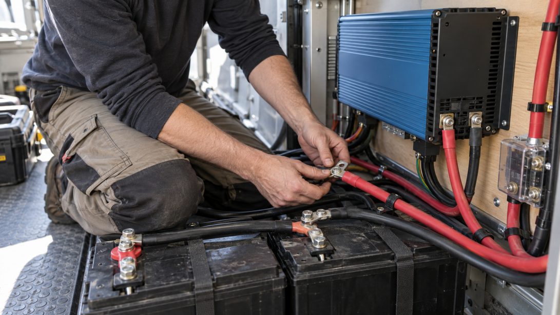
A small, temporary battery-voltage dip under load can be normal. The important comparison is whether the load-side voltage is much lower than the battery-side voltage. A large difference points toward cable length, cable size, a poor crimp, a loose terminal, corrosion, or resistance in a protective device.
For example, if the battery measures 12.4V while an inverter is running but the inverter terminals measure 11.7V, the 0.7V loss is in the path between them. Do not solve that result by changing the battery first. Inspect the complete path, including the positive and negative conductors and each connection.
Size the battery for continuous and startup demand
A usable plan has two separate checks:
Continuous demand: the current the load draws after startup.
Surge demand: the brief current required to start a motor, compressor, pump, or inverter-fed appliance.
The lower limit comes from the weakest component. A battery with a high advertised capacity does not make an undersized cable, fuse, inverter, or BMS suitable for a high-current load.
Use the manufacturer’s continuous-current rating for the battery and BMS. Keep the expected continuous current below that rating with sensible margin, and verify the surge requirement separately. Do not treat a short-duration BMS protection limit as a normal operating target.
A 12V system becomes current-heavy quickly. A 1,200W AC load at an assumed 90% inverter efficiency and 12.8V battery voltage would require about 104A before startup surge. That can exceed the continuous limit of a single battery or expose losses in the wiring even when the battery’s amp-hour label looks adequate.
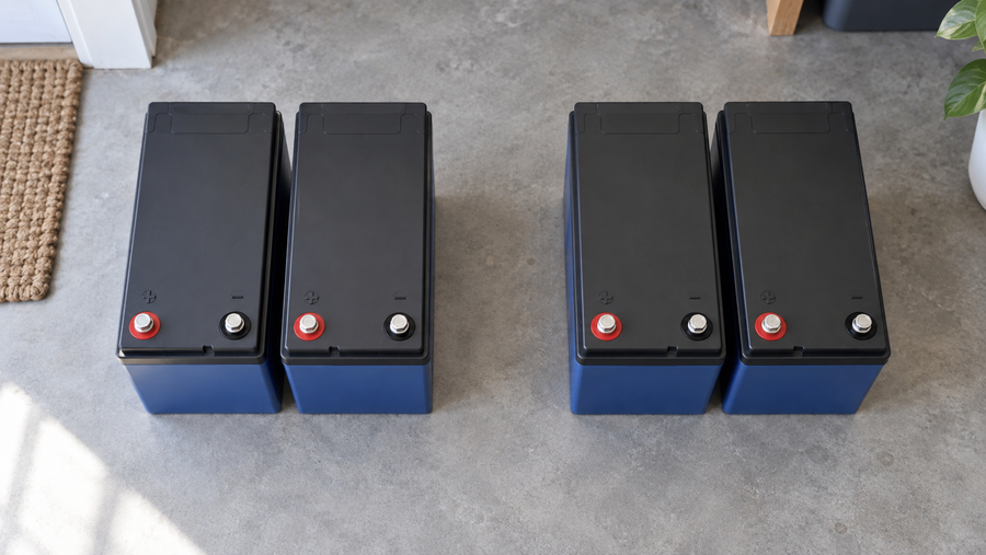
The Vipboss 12V 105Ah Bluetooth LiFePO4 battery has a 12.8V nominal voltage, 105Ah capacity, and built-in 100A smart BMS. The 105Ah figure describes capacity, not output current, and the BMS rating alone does not establish suitability for every high-load application. Before pairing the battery with an inverter or motor load, confirm its exact continuous discharge specification and surge behavior, then match those limits to the inverter, cables, fuse, and operating temperature.
For a compact 12V installation whose verified load stays within the applicable current limits, you can review the Vipboss 12V 105Ah Bluetooth LiFePO4 battery and confirm its current specifications before purchase or installation. Do not bypass the BMS or replace a fuse with a larger one simply to stop shutdowns.
If the load is large and continuous, compare a higher-voltage design before adding more 12V wiring. At the same power, a 24V system draws about half the current of a 12V system, while a 48V system draws about one quarter, before efficiency differences. The inverter, charger, batteries, protection, and loads must all be compatible with the selected system voltage.
Account for state of charge and temperature
The same load can behave differently as the battery’s state of charge and temperature change. A battery near full charge may start a load successfully, while the same battery later in its discharge can show a deeper voltage dip or trigger low-voltage protection.
If the system works when fully charged but the inverter shuts down later, compare the battery voltage and load-side voltage at both times. Check the battery monitor or BMS data as well. Voltage alone is not an exact state-of-charge gauge for LiFePO4 chemistry, especially during a load or soon after charging.
Cold conditions can also reduce available discharge output and increase voltage sag. Include the actual operating temperature when judging whether the system can support the load.