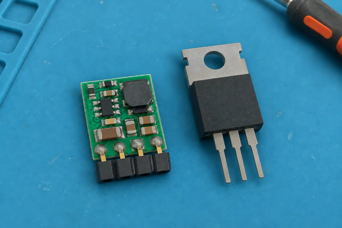

A buck converter is itself a switching voltage regulator, so the choice is between switching and linear regulation for your step-down DC load. Neither is always better: compare both candidates at the required input and output voltages, across the load profile, and against the load’s heat and noise limits. For a 12V battery example of source voltage and load planning, see the 12V system planning guide.
Compare losses and heat at your operating point
A linear regulator controls its output by dropping the voltage across a pass element. As a general idealized estimate, that element dissipates (VIN − VOUT) × IOUT. For example, greater voltage drop or load current means more power converted to heat in the pass element. This estimate does not include the regulator’s other losses, so use the device’s thermal specifications to judge actual temperature and allowable operation.

A buck regulates by switching a transistor and transferring energy through an inductor. Switching reduces transistor loss compared with operating it as a linear pass element, but a real buck still has conduction and switching losses. The topology alone does not tell you its efficiency at a particular load.
Compare each candidate’s efficiency data at your intended input voltage, output voltage, and load current. Then check thermal data for the same operating conditions. If the linear regulator’s estimated dissipation or device-specific thermal data exceeds what your application can accommodate, favor a candidate with lower losses there. If the buck’s measured or specified efficiency and thermal performance do not improve the outcome at your actual operating point, its switching topology alone is not a reason to choose it.
Check input headroom and operating limits
For a linear regulator to maintain its output, the input must remain above the output by at least the device’s dropout voltage under the relevant load and conditions. Check dropout across the input range you expect. If the available input falls below that requirement, the regulator cannot maintain the requested output throughout that part of the range.
For a buck, check the specified input range and other operating limits, including duty-cycle and minimum-on-time constraints where applicable. If the required input/output combination falls outside those limits, that buck is not suitable for the required range. Do not substitute a generic input-to-output headroom rule for the candidate’s specifications: the limits vary by device. The dropout definition and its device-specific variation help explain why the linear check must use the actual part’s data.
Match noise to the load
Linear regulators generally have very low output ripple, while switching supplies usually have some output ripple. That is a qualitative tendency, not a complete ranking of total noise or electromagnetic interference, and individual devices and circuits vary. A technical comparison of regulator ripple describes this distinction without making ripple a universal performance guarantee.

First determine whether the load is sensitive to supply variation, and at what frequencies. Then compare the candidates’ ripple and noise specifications over the relevant frequency range. If the load’s limits are tighter than a candidate’s documented performance, that candidate may not meet the requirement; a low ripple figure alone does not establish low total noise or EMI.
Include light-load periods
Compare performance across the load profile, not only at peak current. Some switching regulators use power-saving modes at light loads. These modes can improve light-load efficiency while increasing output ripple, so weigh both results against the load’s requirements. The light-load mode tradeoff is one reason to inspect the particular device’s operating-mode and efficiency data.
Minimum-load requirements are also device-specific. Check each regulator’s documentation for whether a minimum load applies, and compare efficiency and ripple at the loads where the application spends time. If a switching regulator’s light-load ripple exceeds the load’s tolerance, that may rule it out even when its efficiency is favorable. If the linear regulator’s low-load efficiency or minimum-load behavior better fits the actual profile, that can shift the choice toward linear regulation.
Make the choice from the constraints
| Check | Linear regulator | Buck converter |
|---|---|---|
| Heat and efficiency | Estimate pass-element loss from voltage drop and output current, then check the device's thermal data | Check efficiency and thermal data at the intended input, output, and load |
| Input operating limits | Confirm enough input headroom for the specified dropout under load | Confirm the specified input range and applicable duty-cycle or minimum-on-time limits |
| Noise | Compare ripple and noise against the load's frequency-specific limits | Compare ripple, noise, and operating mode against those same limits |
| Light-load periods | Check efficiency and any device-specific minimum-load requirement | Check light-load mode, efficiency, and ripple |
The table is a screening guide; the actual candidates' specifications decide each row.
Use the required input range, output, and full load profile to screen both candidates. Eliminate any device that cannot maintain regulation within its specified operating limits. Among the remaining options, compare efficiency and thermal data at the relevant operating points, then check noise against the load’s frequency-specific needs and include light-load behavior. The better choice is the device that meets those conditions in your application, not the topology with the broadest general reputation.
FAQs
Is a buck converter a type of voltage regulator?
Yes. A buck converter is a switching voltage regulator, while a linear regulator uses a different regulation approach.
How do you compare heat and efficiency for a buck converter and a linear regulator?
Compare efficiency and thermal data at the input voltage, output voltage, and load currents your application will use. A linear regulator’s pass element has an idealized dissipation of (VIN − VOUT) × IOUT, while a buck also has real switching and conduction losses, so neither topology alone determines the result.
What input-voltage limits should you check before choosing a regulator?
For a linear regulator, check that the input stays above the output by at least the device’s dropout voltage under the relevant load and conditions. For a buck converter, check its specified input range and applicable operating limits, such as duty-cycle and minimum-on-time constraints.
Can light-load operation change which regulator is preferable?
Yes. Some switching regulators use light-load power-saving modes that improve efficiency but increase output ripple; minimum-load requirements are device-specific. Compare efficiency and ripple across the load profile your application actually uses.