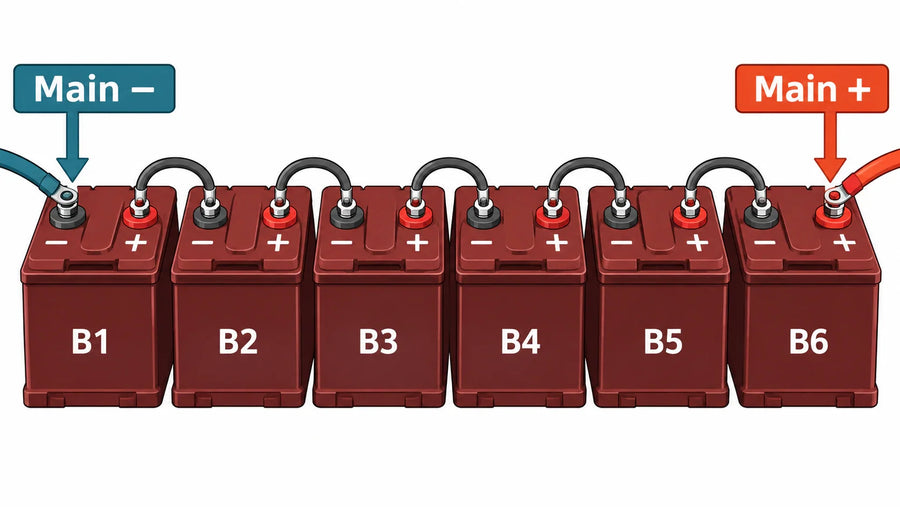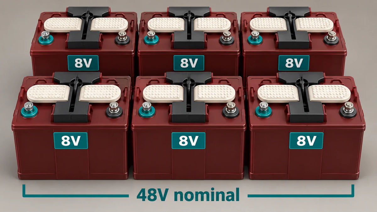

Connect six nominal 8V batteries in series, using five jumpers from one battery's positive terminal to the next battery's negative terminal. With the batteries numbered B1 through B6 in that order, B1 negative is pack negative and B6 positive is pack positive. The nominal voltages add: 6 × 8V = 48V.
Understand the six-battery series layout
B1–B6 identify six complete 8V batteries along the electrical sequence. J1–J5 identify the five external jumpers between them. These labels describe the connections, not fixed positions in the battery tray; the connection table below lists each jumper and its two terminals.
The Department of Energy's electrical fundamentals handbook explains positive-to-negative series connections and the addition of their voltages. Here, each 8V battery is a complete unit in the series string. Connecting six such units gives 48V nominal; it does not mean every meter reading will be exactly 48.0V.
Prepare the cart before changing cables
Confirm that the cart uses a six-battery 8V configuration. Read the voltage and polarity markings on all six batteries, photograph the existing connections, and identify the main vehicle leads separately from jumpers, charger wiring, and accessory wiring.

Turn the key off, secure the cart against movement, and follow its service manual for charger disconnection, any Tow/Run setting, and battery isolation before removing or fitting cables. Caltrans electrical guidance calls for disconnecting batteries and other power sources before electrical work. An isolated battery still has live terminals: keep tools and loose cable ends from bridging them, and use insulated tools and the protective equipment specified for the batteries.
Obtain the cable specifications, terminal torque, and disconnect/reconnect sequence for the actual cart and battery terminals. If the existing wiring or isolation procedure cannot be identified, have a qualified golf-cart technician establish it before proceeding.
Make the five series connections
With the vehicle and charger isolated according to their instructions, label the batteries B1–B6 along the intended series path. Read the terminal markings directly; battery orientation and cable color are not substitutes for polarity labels.
| Jumper | First terminal | Second terminal |
|---|---|---|
| J1 | B1 positive (+) | B2 negative (-) |
| J2 | B2 positive (+) | B3 negative (-) |
| J3 | B3 positive (+) | B4 negative (-) |
| J4 | B4 positive (+) | B5 negative (-) |
| J5 | B5 positive (+) | B6 negative (-) |

Install and secure those links using the specified cables and terminal torque. Follow the same electrical sequence even if the batteries sit in two rows or face different directions.
The two endpoints left outside the jumper chain are B1 negative and B6 positive. These are the designated pack outputs for the cart's negative and positive supply leads respectively. Do not join them with a sixth jumper: that would short the battery string. Keep the vehicle supply disconnected until the checks below are complete. Restore charger and accessory wiring only to the locations identified in the cart's wiring diagram.
Verify voltage and polarity before reconnecting the cart
First trace all five jumpers against the table. Check that no cable connects opposite terminals of the same battery, and that connections are secure and exposed conductors cannot touch unintended terminals.
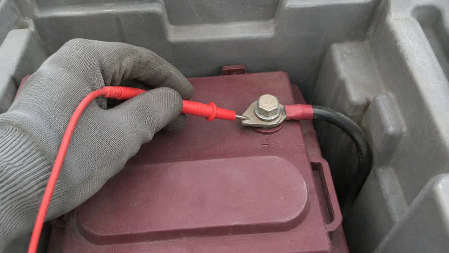
Use a digital multimeter and leads rated for the expected voltage. Put the black lead in COM, the red lead in the voltage jack, and select DC volts with a sufficient range. Never measure voltage with the lead in an A or mA socket. These settings follow Fluke's DC voltage measurement instructions.
Touch the black probe to B1 negative and the red probe to B6 positive, keeping the probe tips from bridging terminals. The reading should be positive and consistent with the battery manufacturer's voltage guidance for the pack's charge state and measurement conditions.
- A negative reading: check the meter leads, probe placement, battery markings, and jumper sequence before connecting the cart. Merely swapping the probes does not verify that the vehicle leads are correctly assigned.
- Zero or an unexpected voltage: leave the cart disconnected and recheck the measurement setup and all six battery connections. Resolve the discrepancy before restoring power.
Remove the probes, then reconnect the cart using its specified sequence. Replace terminal covers and complete the manufacturer's return-to-service checks.
FAQs
How many jumper cables connect six 8V batteries into a 48V pack?
Five inter-battery jumpers form the series string. The cart's main positive and negative supply cables are separate connections at the two ends.
Can the batteries be arranged in two rows?
Yes. The tray layout does not change the required series connections. Follow the numbered terminal-to-terminal assignments and use the cart's diagram for physical cable routing and other vehicle connections.
Does this six-battery layout apply to a single lithium conversion pack?
A single conversion pack has its own pack connections. For example, the Vipboss 48V 150Ah lithium conversion kit uses a 51.2V, 150Ah LiFePO4 battery; use the kit's installation layout for that configuration, while the five-jumper series arrangement describes six separate 8V batteries.