
Connect a golf cart voltage reducer's marked DC input to the cart's documented full-pack supply points, and its marked output to accessories that match the reducer's output voltage. For either a 36V or 48V cart, confirm the actual input-voltage range, terminal functions, circuit protection, and any enable wiring before making connections. There is no universal terminal layout or wire-color code.
Match the reducer to the pack and accessories
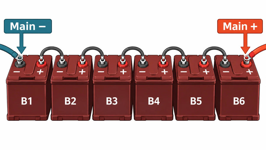
Check the pack's operating and charging voltage range against the reducer's permitted input range. A system label such as 48V is not its highest possible voltage. For example, the Vipboss 48V 150Ah lithium conversion kit uses a 51.2V nominal LiFePO4 pack. When selecting a reducer for that kit, use the battery's actual voltage specifications, including charging conditions if the reducer remains connected during charging.
Check the output separately. A reducer intended to supply 12V accessories must provide a suitable 12V output, but not every reducer has that output. Match the accessories' required voltage and combined current demand to the selected unit, including documented startup loads.
Before installation, obtain the reducer's terminal diagram and the cart's wiring instructions. Identify input positive and negative, output positive and negative, and any enable or remote-control terminal. Some units use a shared negative; others provide an isolated output. Do not add a connection between input and output negatives or use the chassis as a return unless the instructions call for it.
Wire the input, output, and controls
-
Isolate the equipment. Switch off the cart, disconnect the charger, and isolate the vehicle supply using the cart and battery procedures. A key-off state alone is not isolation. Battery terminals remain live, so keep loose conductors and tools from bridging them.
-
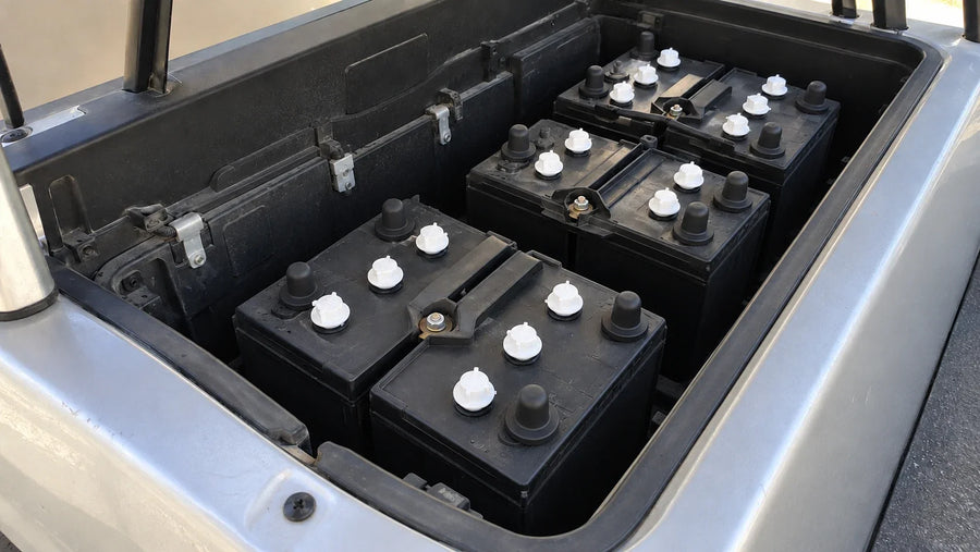
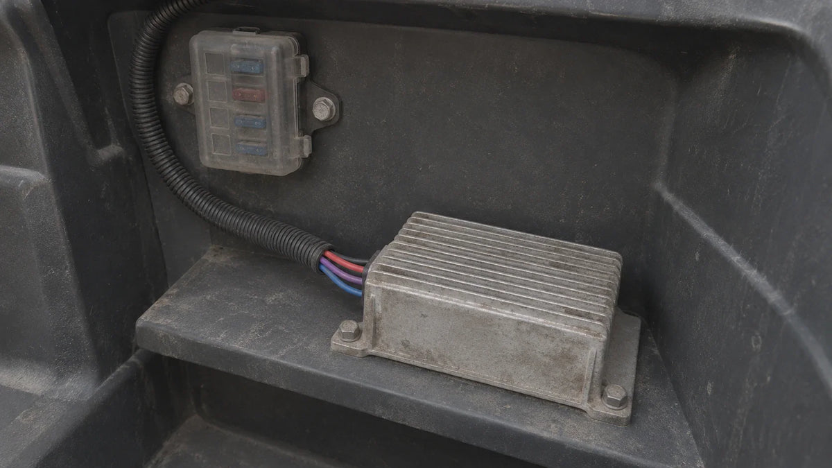
Prepare the mounting and wiring. Follow the reducer's mounting, ventilation, cable-size, and terminal requirements. Route wires away from moving parts, abrasion, and exposed battery connections. Identify the approved pack connection points before cutting or attaching cables.
-
Provide the specified input protection. Fit the specified fuse or breaker in the positive input supply path at the prescribed location. Its rating and the wire specification must come from the equipment requirements; the reducer's output-amp rating alone does not define the correct input fuse.
-
Connect the input and output paths. Connect the reducer input to the documented pack supply points with the required polarity. Connect its output and return to the accessory distribution circuit as shown in the reducer and cart diagrams. Fit output-branch protection where the installation requires it. Keep the supply isolated while making these connections.
-
Wire any enable control. If the reducer has an enable or remote terminal, use its specified signal voltage and connection arrangement. If there is no such terminal, follow the approved main-input switching arrangement when keyed operation is required. Do not assume the key switch can carry the reducer's input current.

DC/DC terminal arrangements differ. The manufacturer's diagram takes priority over a generic cable-color example; the DC/DC converter application guidance explains the need to follow the correct connection arrangement and avoid wiring faults.
Inspect and test before normal use
Check input and output assignments, polarity, protection, cable security, and terminal covers. Confirm that accessories are connected to the output rather than directly to the higher-voltage input circuit.
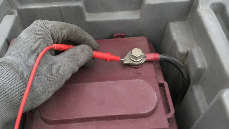
Restore power using the equipment's specified sequence. Where the reducer's commissioning instructions call for an unloaded output check, measure it before connecting the accessory load. Use a suitably rated meter in DC-voltage mode, with the leads in the voltage and COM sockets. Compare the output with the reducer and accessory specifications, then test the intended loads and key-on/key-off behavior.

If the output is unexpected, a fuse opens, or a connection heats, stop and isolate the equipment before investigation. Resolve uncertain terminal functions or missing specifications before returning the cart to service.
FAQs
Can a reducer marked 36V/48V be used on any pack in those system classes?
Not from that label alone. Its specified input range must cover the actual pack's operating voltage and any charging voltage it will encounter. Check the battery and reducer documentation together.
Do all golf cart voltage reducers output 12V?
No. Output voltage is a model-specific specification and may be fixed or adjustable. Choose and, where applicable, set the output to match the connected accessories.
Should input negative, output negative, and the chassis be connected together?
Only where the installation instructions specify those connections. Shared-negative and isolated-output units have different arrangements, and the cart chassis is not automatically the designated return path.