To build a portable 12V LiFePO4 solar generator, size it for your loads, choose a battery, solar panel, charge controller and any AC inverter whose ratings work together, then assemble separate, protected charging and load branches. The panel feeds the controller's PV input, not the battery terminals. The controller charges the battery; an inverter or DC outlet draws from its own appropriately protected battery branch. The exact terminals, wire sizes, fuse ratings and energizing order come from the components you actually select.
1. Size the loads before buying parts
List each device's watts and expected hours of use. Multiply watts by hours for each device, then add the watt-hours (Wh). Decide how many days the station must work without useful sunlight. Compare that delivered-energy target, with conversion losses where applicable, against the battery's usable energy rather than its amp-hour label alone. For AC devices, add the watts of loads that may run together and check any starting surge against the inverter's continuous and surge ratings. These are separate energy and power checks in the University of Maryland solar sizing guide.
For example, a 40W device used for four hours and a 10W device used for eight hours need about 240Wh per day (160Wh + 80Wh) at their stated inputs. Two days without charging require 480Wh delivered, before any conversion loss or usable-capacity limit. This is a load calculation, not a recommendation for a particular battery.
Estimate the solar energy you must replace during the available charging period. Use the location and season's peak-sun-hours and an appropriate system-yield estimate; panel watts = target Wh / (peak-sun-hours × yield). Then check the chosen controller's PV voltage, current and power limits against the complete panel arrangement, including the panel's open-circuit voltage under the conditions specified for that controller. A nominal “12V” label alone does not establish compatibility.
2. Draw the branches and select components

For a single-battery portable station, use this functional layout, then map every connection to the selected equipment's diagrams:
solar panel(s) ── PV branch ──> charge controller PV input
charge controller battery output ── protected battery branch ──> 12V LiFePO4 battery
12V LiFePO4 battery ── separate protected branch ──> inverter ──> AC loads
12V LiFePO4 battery ── separate protected DC branch ──> DC outlets/loads, if used
The University of Alaska solar manual's system diagrams distinguish the panel-to-controller path, controller-to-battery path and battery-fed load path. Some controllers also have a DC load output: use it only when that controller explicitly supports the intended load and current. Otherwise, plan the separate protected battery-fed DC branch shown above. Use an inverter's built-in AC outlets for portable AC loads; fixed AC wiring is a different installation task.
Choose the battery by usable energy and allowable discharge current. Check that the controller's LiFePO4 charging settings and maximum charge current fit the battery requirements. Check that the inverter's DC input range, continuous input demand and surge demand fit the battery and its protection limits. Choose the enclosure, connectors and any disconnects for the actual components and operating environment; maintain the clearances and airflow their manuals require.
3. Size wire and overcurrent protection for each branch

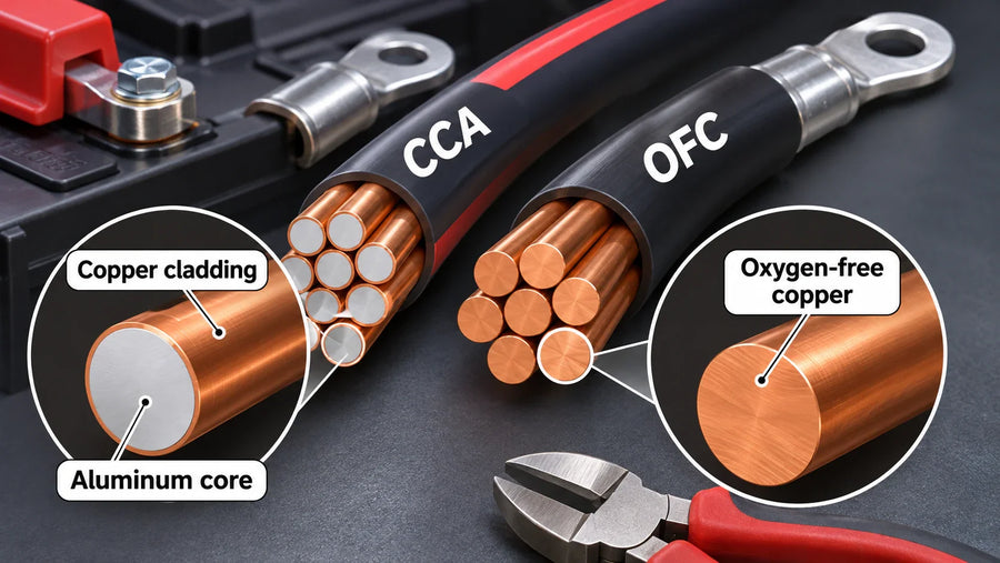
Do this branch by branch, before making connections. Record each branch's maximum expected current, positive-plus-negative conductor length, wire insulation and installation conditions. For the PV branch, obtain the panel's short-circuit current and the array configuration. For the inverter branch, use its documented maximum DC demand or calculate an estimate from output power, minimum DC input voltage and efficiency, then check the actual manual. Select conductor type and size for current-carrying capacity after applicable temperature and grouping corrections, and check voltage drop over the round-trip length. The University of Maryland wiring and fusing guide explains those inputs and the PV and inverter circuit calculations.
Protect each battery-fed positive branch with a DC-rated fuse or breaker chosen for the wire and connected equipment. Its current rating must protect the conductor while meeting the device's specified protection requirement; its voltage and interrupt ratings must suit the battery circuit. Locate protection at the power-source end as required by the applicable equipment instructions and electrical rules. This DC protection reference explains conductor protection, source-side placement and interrupt capacity for marine systems; its boat-specific distances and exceptions are not universal rules for a portable station. Determine PV-side protection separately from the panel configuration and possible backfeed: one panel and multiple parallel strings can have different requirements. Do not pick one fuse or wire gauge for every 12V build. If the selected wire, fuse and equipment ratings cannot be reconciled, change the component or branch design before assembly.
4. Assemble and check before use
- Mount and route. Secure the battery, controller, inverter and protected distribution points. Keep the specified ventilation paths open. Route and support each branch so conductors cannot rub on sharp edges or strain terminals. Keep the PV source disconnected or covered while preparing connections.
- Identify every terminal. Match battery positive and negative, controller battery and PV inputs, inverter DC input and each load branch to the actual component diagrams. Label the conductors; check polarity before terminating them. The diagram above describes roles, not terminal positions on a particular product.
- Install the selected conductors and protection. Complete the controller-to-battery, inverter-to-battery and any separate DC-load branches using their individually selected wire and protective devices. Make the PV connection only at the controller's designated PV input. Use the connector type and tightening requirements specified for each component; leave sources isolated until the specified checks are complete.
- Check, then energize in the documented order. Compare every connection, polarity, fuse rating, cable size and controller charge setting with the component specifications. Follow the selected controller's battery/PV connection order; some controllers require battery connection before PV for voltage detection, but that order is not universal. With the installation checks complete, enable one branch at a time and verify the controller's charge indication and each load under the expected operating conditions. Stop and isolate the system if a protective device trips, a connection heats abnormally or a component reports a fault; resolve the cause before continuing.
The build is complete only when the selected battery, controller, panel, wiring, protection and loads form a compatible system under their documented limits. A layout or calculation cannot replace a missing device rating or establish an unknown electrical connection.