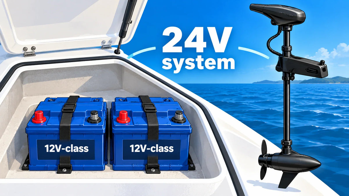

Connect two suitable 12V-class batteries in series to supply a 24V trolling-motor system. Join Battery 1 negative to Battery 2 positive with one jumper. The remaining terminals are the bank outputs: Battery 1 positive to the motor's positive supply path, and Battery 2 negative to the motor's negative lead. Include the circuit protection specified for the motor in that supply path.
Choose batteries intended to work together
Use batteries that the manufacturer allows to be connected in series, and follow its requirements for matching model, capacity, condition, and state of charge. For lithium batteries, confirm series support for the complete battery and its battery-management system, not just the chemistry name. The motor and charging equipment must also support the completed bank's voltage range.
If you are selecting LiFePO4 batteries for this arrangement, the Vipboss 12V 105Ah battery supports series expansion up to four units, making a matched two-battery series bank a supported configuration. This particular model is 12.8V nominal, so two of it in series total 25.6V nominal. That is a model-specific example, not a definition of every battery sold in the 12V category.
For whichever batteries you use, calculate the bank's nominal voltage from their actual specifications. The “24V” motor-system class is not a promise that the assembled bank will measure exactly 24.0V at all charge states.
Prepare the bank before wiring
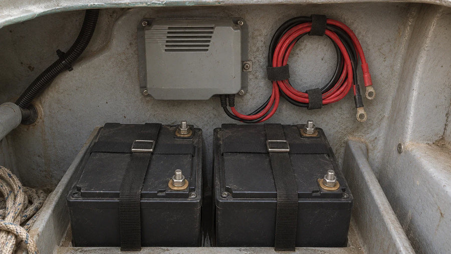
Turn the motor off and disconnect it from the battery supply. Disconnect charging equipment according to its instructions before changing battery connections. Keep the motor disconnected while assembling and checking the bank. Secure the batteries and keep loose tools or cable ends from bridging terminals.

Identify the plus and minus markings directly on each battery and label the units Battery 1 and Battery 2. Use the conductor size, terminal torque, and protection specified for the motor, cable run, and battery terminals. A general series connection does not establish a single breaker size or wire gauge for all trolling motors.
Connect the jumper and motor supply
Make the one inter-battery jumper from Battery 1 negative to Battery 2 positive. Do not connect positive to positive and negative to negative; that would create a parallel arrangement rather than the intended series bank.

Battery 1 positive and Battery 2 negative are now the two outer supply terminals. Prepare the positive motor-supply path from Battery 1 positive through the specified circuit protection, and the negative return to Battery 2 negative. Keep the motor isolated until the bank checks are complete. When a plug and receptacle are fitted, follow their terminal assignments as well as the motor diagram.
The battery numbering can be reversed in another valid drawing, so use a consistent set of labels throughout the installation. Do not combine one diagram's jumper labels with another diagram's motor-terminal labels. Trolling-motor series connection guidance shows why the motor connects across the two remaining endpoints.
Check protection, voltage, and polarity
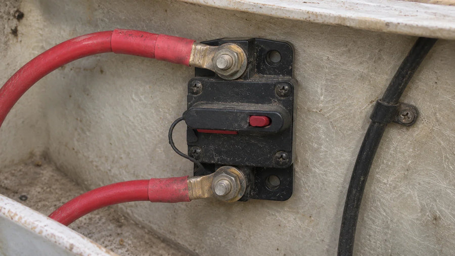
Install the breaker or fuse in the location required by the equipment instructions. Select protection and cable size together for the motor's current demand and cable run; do not derive the breaker rating from battery amp-hour capacity. Tighten and protect the connections using the applicable specifications.
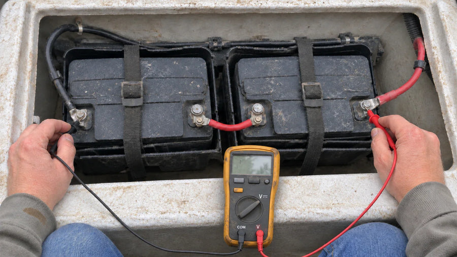
Before reconnecting the motor, inspect the jumper and both output assignments. Measure the bank across Battery 1 positive and Battery 2 negative using a suitably rated digital multimeter in DC-voltage mode. Put red in the voltage socket and black in COM, then place red on Battery 1 positive and black on Battery 2 negative. Never use a current socket for this voltage measurement.
Check for a positive reading appropriate to the batteries and measurement conditions. A negative or unexpected reading requires checking the meter setup, terminal labels, and wiring before connecting the motor. A correct no-load voltage alone does not establish that every connection will perform correctly under load.
Reconnect using the equipment's procedure. Test the motor only under the operating conditions specified by its manufacturer, and stop if connections heat, protection trips, or operation is abnormal.
FAQs
Does series wiring double amp-hour capacity?
For two matching batteries, series wiring adds their nominal voltages while the bank's amp-hour rating remains that of one battery. Parallel wiring serves a different purpose and does not create the required higher-voltage supply.
Are all batteries labeled 12V actually rated at 12.8V?
No. Use the nominal voltage stated for the particular battery and chemistry. The 12.8V figure in this article belongs to the named Vipboss example; it is not a universal rating for 12V batteries.
Can I power 12V electronics from one battery in this bank?
That connection selectively loads one member of the series bank. Use an appropriate accessory-power arrangement, such as a converter rated for the full bank input and the electronics' required output, instead of assuming a single-battery tap is suitable.