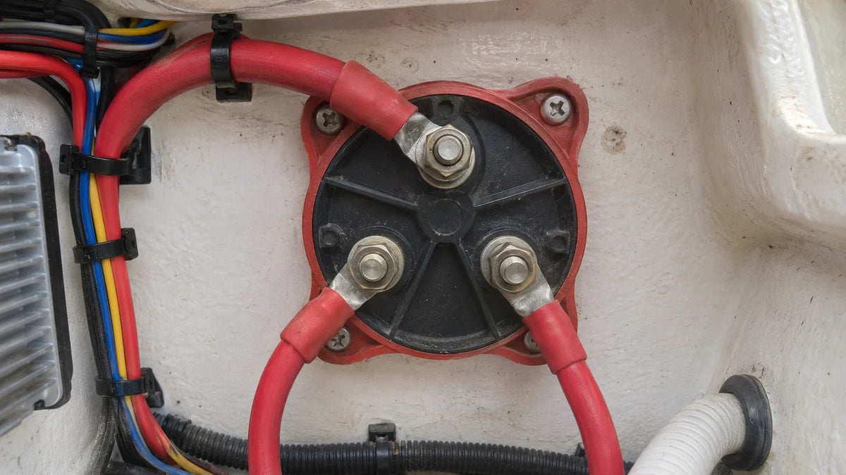

Start with the diagram for your installed 1-2-Both-Off switch and identify which battery and circuit each terminal serves. In the documented example below, battery 1 positive goes to terminal 1, battery 2 positive to terminal 2, and COM to the illustrated engine circuit. That example does not establish where a different boat's house loads or charging conductors belong. Map those circuits from the installed switch and vessel diagrams before making connections.
Identify the switch terminals and positions

Use the diagram for the exact switch model to locate battery inputs 1 and 2 and the common terminal, often marked COM. The documented switch installation diagram shows the battery positives connected to terminals 1 and 2 and COM connected to the illustrated engine circuit. It also shows different arrangements for different engine and battery-bank configurations.
For that documented switch series, position 1 selects battery 1, 2 selects battery 2, BOTH combines the battery inputs, and OFF disconnects the switched circuit. Other switches may differ in terminal layout or operation, so identify the markings and connections in the diagram for the switch installed on your boat.
Connect the batteries and circuit conductors

- Isolate the batteries. Remove the positive leads from the battery banks before making switch connections, as directed by the switch installation instructions. Keep the engine stopped while wiring.
- Map the conductors. Identify each battery positive, the engine starter-feed path, house-load feed, and charging conductors. If you use the Vipboss 12V 105Ah battery as one bank, identify its positive lead for connection to the corresponding battery input shown on your installed switch diagram.
- Connect the battery inputs. Connect each battery positive to the input designated for that battery. On the documented switch design, these are terminals 1 and 2, respectively. Confirm polarity and terminal identity against the actual diagram before tightening; do not infer them from physical position alone.
- Route the switched circuit. On that documented design, connect COM to the illustrated engine circuit. This is a model-specific example, not a universal COM destination. For other switch designs or vessel topologies, identify the engine, house-load, and other switched circuits from the installed switch and vessel equipment diagrams, then route each conductor as those diagrams show. A separate example diagram depicts engine and load connections separately and says it is a guide, not a full electrical-system wiring diagram.
- Handle charging conductors separately. Trace the alternator output and any regulator or field-disconnect wiring using the actual alternator, regulator, engine, and switch diagrams. Some switch configurations use a field-disconnect accessory for particular alternator arrangements; it is not a universal connection. The cited switch instructions also say to stop the engine before moving that model to OFF. Do not assume an alternator lead belongs on COM.
- Size and tighten connections. Use cables sized for the loads they carry, support them so their weight does not strain the switch studs, and tighten electrical connections correctly. The installation instructions require load-appropriate cable sizing and correctly tightened connections but do not provide one cable gauge or torque for every installation.
Protect marine DC conductors
Overcurrent protection depends on the conductor and circuit. A 1990 ABYC E-9 excerpt distinguishes cranking-motor conductors from other ungrounded conductors and describes protection placement and exceptions for other conductors. This historical excerpt does not establish current requirements for every boat or a universal fuse location or rating. Determine protection for each circuit under the current requirements applicable to the boat and its jurisdiction.
After wiring, inspect terminal mapping and polarity against the equipment diagrams before restoring battery positives. Verify switch positions only in the manner allowed by the installed switch instructions and the vessel’s engine and charging-system requirements.