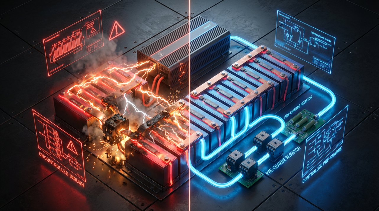

A pre-charge resistor tames the violent current spike when your lithium battery first connects to an inverter, protecting your BMS, contactors, and power electronics so the system can start smoothly and deliver full power all day.
Imagine closing the main battery switch, hearing a sharp click from the battery case, the display going dark, and the inverter never even reaching its splash screen. Maybe it starts on the second or third try, until one day the protection electronics in the battery give up and the system stays dead. The fix is not a bigger battery or a “stronger” inverter, but a simple, correctly sized resistor that lets the whole system wake up gently instead of being punched at every startup.
The Invisible Punch Between Inverter and Battery
On any serious inverter or motor drive, the DC input does not look like a calm load at startup; it looks like a large, empty bucket made of capacitors. The instant you connect a stiff lithium bank, those capacitors try to jump from zero volts to battery voltage, and the only things limiting current are wiring resistance and whatever the BMS or contactors can survive.
In high-voltage DC systems, pre-charge is a controlled power-up mode that slowly charges these capacitive loads so inrush current stays within safe limits, dramatically reducing stress on semiconductors, contactors, and fuses. The same physics that drives pre-charge in electric vehicles and industrial drives applies directly to a 48 V off-grid inverter: current into a capacitor rises with both capacitance and how fast you try to force the voltage across it to change.
A classic example uses about 11,000 uF of input capacitance: at only 28 V the inrush over roughly 10 milliseconds is around 31 A, but at about 610 V the same capacitance can draw roughly 670 A in that same window if you connect it with no pre-charge, and even higher if the voltage rises faster. That is a difference of two orders of magnitude in stress, set by voltage and dV/dt rather than your “normal” operating current, which shows why higher-voltage lithium stacks and big inverters are so unforgiving when you connect them casually.
To your BMS, that spike looks a lot like a short circuit. The protection electronics are trying to enforce cell limits, shunt currents, and contactor ratings, but a dead-cold inverter input can demand hundreds or thousands of amps for a few milliseconds. Every hard start-up eats away at MOSFET margins, heats contact surfaces, and can eventually turn a nuisance trip into a silent failure.
What a Pre-charge Resistor Actually Does
The pre-charge resistor is the shock absorber between your battery and that empty capacitor bank. In practical systems, it is a robust power resistor wired in series with a small pre-charge switch so the inverter’s DC bus charges gently before you ever let it see full battery current. Resistors are widely used in chargers and power electronics specifically to limit inrush current and reduce stress on rectifiers, switches, and batteries, improving safety and reliability over many thousands of cycles, as highlighted in work on resistors protecting battery chargers.
In EV-style high-voltage systems, the battery management system (BMS) first closes the negative contactor and a dedicated pre-charge contactor, forcing current through a resistor to charge the inverter or motor controller’s DC bus capacitor. Once the bus voltage is within about 50 V or roughly 10% of pack voltage, the BMS closes the positive contactor, opens the pre-charge contactor, and only then declares the vehicle ready for torque, as described in detail for EV contactor and precharge operation. The resistor has already done its job and is bypassed; under normal running it sees no current.

The same arrangement can sit between your lithium rack and an off-grid inverter. The battery connects first through the pre-charge resistor so the inverter’s input capacitors ramp most of the way up to battery voltage at a controlled current. Only after that ramp does the main contactor or breaker close to deliver full power. Because the inrush is capped, the BMS no longer sees a brutal step demand, so its current shunts, internal FETs, and measuring circuits stay in their comfort zone instead of being hit at the edge of their protection curve. Pre-charge resistors in EV charging paths are explicitly used to protect the BMS from surges and keep charging within safe electrical limits, exactly the same role you need in a lithium retrofitted power system.
There is an equally important mechanical side. Closing a high-voltage contactor into a discharged capacitive load without pre-charge can produce severe arcing and contact pitting, and repeated abuse can literally weld the contacts together. Application notes for solid-state pre-charge drivers point out that pre-charging the DC link before closing the main contactors is essential to avoid arcing, pitting, and contact welding in high-voltage battery systems, and that a properly controlled pre-charge path dramatically reduces this risk by taking the worst of the surge through a resistor and solid-state switch instead of through the main contactors, as shown in designs like TI’s TPSI3050-Q1 pre-charge driver.
Inside the Pre-charge Sequence: How Your BMS Should Bring the Inverter Online
Whether you are looking at an EV traction system or a large off-grid inverter, the healthy power-up sequence follows the same script. The BMS or system controller wakes the low-voltage side, runs self-checks, and then starts the high-voltage sequence by closing the negative contactor and the pre-charge contactor. Current flows through the pre-charge resistor into the inverter’s DC link capacitor, and the controller continuously monitors DC bus voltage.
Only when the DC bus rises to within roughly 10% of pack voltage does the controller close the positive main contactor and open the pre-charge contactor, at which point full high-voltage current can flow to the inverter with almost no voltage gradient across the main contacts. This control strategy, where pre-charge is considered complete once the bus is within tens of volts of battery voltage and only then are the main contactors allowed to close, is standard in EV systems and is directly documented for EV BMS-controlled precharge sequences.
If anything in that chain fails, the controller refuses to bring the system online. In vehicles, it will set flags like “not precharged” or “precharge failed” and block high-voltage activation to protect the inverter and battery. Field technicians listen for the distinct series of relay clicks at key-on and then verify continuity of the pre-charge resistor when those codes appear, because a failed pre-charge resistor or relay can cause delayed startup or uncontrolled inrush that may weld the main relay contacts, as explained in expert discussions of EV main relays and precharge systems.
If you are building or upgrading an off-grid system, you want exactly the same behavior. A healthy BMS or external controller should be able to bring the inverter online through a defined pre-charge step, verify that voltage has risen as expected, and abort cleanly if the inverter input looks shorted instead of simply slamming the pack into a fault.
Why Lithium Retrofits and Off-Grid Systems Kill BMSs Without Pre-charge
Many legacy off-grid and RV systems were designed around lead-acid batteries that could tolerate large momentary surge currents without any electronics in the way. Drop-in lithium batteries and modern rack packs are different: an internal BMS sits between the cells and the outside world, and its job is to shut down hard when it sees abuse. From a BMS point of view, a large inverter with a cold DC bus capacitor looks like an abusive short every time you connect it.
Pre-charge resistors are already standard in EV charging and drive systems for this reason. They are placed so that, when an EV connects to a charging station or enables its traction inverter, current initially flows through the resistor, which prevents sudden surges that could cause short circuits, overheating, or damage in the charging or drive circuit, while explicitly shielding the BMS from power surges and enabling accurate measurement of battery state so it can adjust charging safely.
On the charger side, resistors are also used for inrush-current limiting, current sensing, and bleed paths to reduce stress on rectifiers and switching devices in battery chargers, which directly benefits battery health by avoiding thermal and electrical abuse during startup and shutdown. This broader role of resistors in protecting charger electronics and connected batteries is emphasized in work on the role of resistors in protecting battery chargers.
Even at far lower voltages than a full EV pack, engineers designing Li-ion chargers integrate a dedicated pre-charge mode specifically to handle deeply discharged cells gently before normal charging starts, because that combination of cold cells and empty capacitors is especially fragile. Integrated CMOS charger designs add this low-current pre-charge stage ahead of the main regulation loop to protect both the cell and the on-chip pass device, underscoring how deeply pre-charge is baked into robust charging practice, even in compact single-cell systems, as shown in a Li-ion charger with integrated pre-charge mode.
When you bolt a large inverter straight onto a lithium bank with only a BMS in between and no pre-charge, you are essentially asking that BMS to absorb all of the inrush current and voltage transients that dedicated pre-charge hardware is meant to handle. The immediate symptoms are annoying—clicking relays, boot loops, nuisance trips—but the long-term result can be scorched contactors, damaged shunts, or failed FETs inside the BMS.
How to Implement and Size a Pre-charge Resistor in a Real System
At the electrical level, a pre-charge path between battery and inverter is simple: a resistor in series with the DC input, controlled by a switch or contactor that is closed only during startup. The challenge is choosing a resistor and switch that can gracefully handle the peak power and energy of each start, and making sure your control logic actually waits for the DC bus to reach a safe level before bypassing that resistor.
Resistor selection always balances resistance value and power rating against acceptable charge time and temperature rise. Higher resistance gives lower peak current but a longer wait before the bus reaches 90–95% of battery voltage; lower resistance charges the bus faster but increases the current and power that the resistor and upstream components must survive on every start. Engineering guidance for charger and pre-charge applications stresses choosing resistors with adequate power and pulse-handling capability, and with construction and mounting that can manage the repeated high-energy hits and resulting heat without cracking or drifting, as discussed in practical notes on resistors used for charger protection.
A useful way to think about sizing is in terms of both instantaneous power and total energy. The peak power in the resistor is roughly the square of the input voltage divided by the resistance value during the first instant of connection, and the energy it must safely absorb during a pre-charge event is approximately half the capacitance times the square of the final voltage. For example, a DC link with around 1,000 uF of capacitance charged up to about 340 V demands on the order of 58 joules from the pre-charge resistor per start; if the resistor is too small or underrated, that energy is enough to damage it from within after repeated cycles, even if it never fails spectacularly on day one.
The switch that drives the pre-charge resistor matters just as much. Traditional designs use an electromechanical relay or small contactor for the pre-charge path, but those devices still face voltage stress and can suffer from arcing or welded contacts if misused. Modern designs increasingly use solid-state pre-charge switches built from MOSFETs driven by dedicated isolated drivers. For example, TI’s TPSI3050-Q1 is an isolated pre-charge driver that controls external FETs in place of a mechanical relay, generating its own isolated bias and providing fast turn-off so a pre-charge path can be implemented as a compact, highly reliable solid-state relay in EV battery systems and industrial power supplies.
Whatever hardware you select, the controller needs feedback from the inverter’s DC bus. The standard strategy is to monitor bus voltage during pre-charge and only close the main contactor once the bus is within a few volts, or about 90–95% of the battery voltage, then open the pre-charge path. This avoids having to interrupt a large DC current through the pre-charge resistor and ensures that the main contactors close into a minimal voltage difference, reducing arc energy and contact wear, a pattern described as best practice for pre-charge in high-voltage DC systems.
Many off-grid builders reach first for NTC (negative temperature coefficient) inrush limiters because they are easy to wire and self-resetting. They start with relatively high resistance when cold, then heat up and drop to a low resistance at full load. This can work well for small auxiliary supplies, but for large inverters there are real drawbacks: the parts run very hot, their behavior changes with ambient temperature, and they need time to cool before they can effectively limit inrush again. In systems that cycle on and off frequently—think generators, automated transfer, or aggressive energy management—an NTC can easily be hot from the last run and offer almost no inrush limiting when you most need it.
In contrast, a fixed pre-charge resistor with explicit control gives repeatable behavior every time you start the system. For very high voltages or large capacitors, designers often use several resistors in series or parallel to spread the energy and voltage stress, and they mount those parts to metal for better cooling. The same discipline that goes into a well-designed EV pre-charge circuit transfers cleanly into a robust lithium off-grid or backup-power installation.
Comparing Common Startup Approaches
Startup approach |
Where it shows up |
Main advantage |
Main drawback |
Direct connect, no pre-charge |
Older lead-acid systems |
Simple, no extra parts |
Huge inrush, high stress, risk of BMS trips and welded contactors |
Fixed resistor plus controlled bypass |
EV drives, serious off-grid systems |
Predictable inrush limit, cheap and robust |
Needs correct sizing and coordination of resistor, switch, and timing |
NTC inrush limiter |
Small supplies, ad-hoc retrofits |
Self-heating gives lower losses at steady state |
Runs very hot, poor performance with frequent cycling or cold variation |
Solid-state or active pre-charge |
Modern EV packs, industrial HV gear |
Fast, repeatable, minimal contact wear |
Higher component cost and more design effort up front |
The more expensive options exist for good reason: field experience from heavy-duty renewable and drive systems shows that upgrading pre-charge components and control can slash failure rates and maintenance downtime, even when nothing else in the power train changes. In that sense, a carefully chosen pre-charge resistor or solid-state pre-charge module often pays for itself long before the rest of the system has aged.

Troubleshooting: Do You Have a Pre-charge Problem?
You do not need an oscilloscope to suspect a pre-charge issue. If your inverter only starts on the second or third try, if the BMS clicks off the moment you close a breaker, or if you see startup error codes but the system runs fine once it finally comes up, inrush is a prime suspect. Those are classic signs that the inverter’s capacitors are demanding more instantaneous current than the BMS or upstream contactors are willing to allow.
In EV diagnostics, technicians look for specific pre-charge status flags such as “not precharged” or “precharge failed” and pay attention to the timing and sound of relay clicks at startup; missing or repeated clicks in the pre-charge relay path point to problems, and a welded main relay often tells a story of uncontrolled inrush that has finally fused the contacts, as recounted in field-oriented explanations of EV main relays and precharge behavior. Off-grid systems may not expose such detailed codes, but an inverter that repeatedly reports DC under-voltage or internal faults right at power-up, while behaving normally when already running, is often suffering from the same underlying issue.
When you suspect pre-charge trouble, start with the basics. Confirm that the pre-charge resistor is actually present, has the expected resistance, and is of a suitable power rating and construction for the job rather than a small general-purpose part pressed into service. Check that whatever device is supposed to drive it—a relay, contactor, or MOSFET array—is being commanded at startup and can withstand the full DC bus voltage when open. And if your BMS claims to implement pre-charge internally, verify with the manufacturer whether its ratings match the size of inverter you are now feeding; many internal BMS pre-charge circuits are designed only for modest OEM loads, not for an oversized aftermarket inverter.
FAQ
Do I really need pre-charge on a low-voltage system?
Even at modest voltages, the combination of a stiff battery bank and large input capacitors can create inrush currents far above the continuous rating of your BMS or contactors. Engineering examples show that increasing voltage on a fixed capacitor from dozens of volts to a few hundred can increase inrush current by two orders of magnitude, and the same dependence on voltage and dV/dt applies at 12 V or 24 V, just with lower absolute numbers. If your inverter is powerful for its voltage and your battery electronics are compact, adding a pre-charge path is cheap insurance.
Can I just “close the breaker slowly” instead of using a pre-charge resistor?
Trying to “feather” a mechanical switch does not change the physics in a predictable way. The arc that strikes as the contacts come together can be intense, and repeated attempts at slow closure can actually increase contact erosion and the chance of welding. High-voltage application notes recommend using a controlled pre-charge path with a resistor and dedicated switch, then closing the main contactors only after the DC bus is nearly charged, to avoid arcing, pitting, and welded contacts in high-voltage battery systems, as in solid-state pre-charge designs like TPSI3050-Q1-based circuits. A proper pre-charge resistor and control sequence gives you consistent, gentle startup every time; manual tricks do not.
Is pre-charge only for EVs, or does it matter in solar and backup systems too?
Pre-charge emerged prominently in EV traction and charging systems, but the underlying need exists anywhere a battery or DC source feeds a big capacitive load. Industrial motor drives, renewable-energy inverters, UPS systems, and large battery chargers all use resistors and controlled startup sequences to limit inrush and protect rectifiers, switches, and capacitors, as emphasized in discussions of resistor roles in protecting battery chargers. If your lithium retrofit includes a serious inverter or drive, you benefit from the same level of startup discipline that modern EVs and industrial drives already take for granted.
Power Up Without the Bang
A lithium retrofit or off-grid power upgrade should feel boringly reliable: close the switch, the system wakes up cleanly, and you get full power without drama. A correctly implemented pre-charge resistor and control sequence makes that possible, turning a destructive current punch into a controlled ramp that your BMS, contactors, and inverter can shrug off for years. Treat pre-charge as a non-negotiable part of the design, and your power upgrade stops being a source of intermittent failures and becomes the quiet, dependable backbone of your energy system.